
Container support

a container and support technology, applied in the field of flexible containers, can solve problems such as leakage of containers, failure of containers, and certain problems encountered

Inactive Publication Date: 2006-04-11
BAXALTA GMBH
View PDF101 Cites 12 Cited by
  • Summary
  • Abstract
  • Description
  • Claims
  • Application Information

AI Technical Summary

Benefits of technology

[0023]According to yet another aspect of the invention, a port closure for the container is provided. The port closure provides a means for providing a sterile and gas permeable barrier over the port. In one embodiment, the port closure has a communication member having a first end and a second end, the first end adapted to be in communication with the container. A stop member is inserted into the second end of the communication member wherein the stop member is made from a porous material. A cover member is provided and receives the second end of the communication member. The cover member is releasably secured to the communication member. In a preferred embodiment, the communication member is a tube made from a thermoplastic material. The stop member is a plug. An elastic band is wrapped about the pouch and the communication member releasably securing the cover member to the communication member. A tamper evident feature can also be incorporated into the port closure.

Problems solved by technology

In the design and use of three-dimensional flexible containers of such volumes, certain problems are encountered.
The large volume of liquid held by the containers exerts a hydraulic force against seams of the container, which in an unsupported state, might be sufficient to cause failure of the container.
The forces associated with such liquid volumes can cause the container seams to fail or rupture, therefore causing leaks in the container.
Accordingly, even a very small leak can be costly in that any seam rupture compromises sterility of the entire contents of the container.
Also, a failure of a container seam can cause literally hundreds of liters of liquid to escape from the container.
This is costly in replacing the lost liquid contents of the container.
Clean-up costs are also encountered.
The stainless steel material is naturally an optical obstruction from seeing into the box.
The door, however, is very small in size and cannot provide a full view of the flexible container within the box.
Similarly, however, these small sight openings do not allow a full view of the container within the box.
Because of the size of the containers, it may be difficult to properly align the container within the box.
While initially properly aligned, the flexible container may shift becoming misaligned during the container filling process.
If misaligned, the container can have unwanted folds that do not properly expand when the bag is filled.
Such container folds caused from misalignment can result in undue stress on the container seams leading to container failure.
If the container is unsupported, it will tend to collapse in horizontal pleats.
In these instances, a horizontal pleating of the container can restrict the desired realignment during the refilling process.
This can result in poor orientation or loss of the effective volume of the container.
It may also result in insufficient support of the container.
While the sachet is a three-dimensional container, the container does not have optimal angular construction between sides of the container.
Accordingly, optimal filling, draining, and re-filling of the container cannot be achieved.
First, the dip tube cannot orient the distal vertical surfaces of the container if the container foot print geometry is more complex than a circle.
In addition, as the container is drained, the walls of the container converge towards the center essentially creating loads of compression on the non-compliant dip tube.
These compressive forces can cause several problems.
The seal between the dip tube and the top of the container can be compromised.
Using a dip tube structure also increases the cost the container system.
One problem that exists in using a sealed silicone tube, however, is that while providing a sterile closure, it does not facilitate the free passage of gases.
This introduces an opportunity to contaminate the tube, and also poses a risk of injury to the operator.
Similar to the sealed tube approach, such fittings provide a sterile closure but do not provide for gas transfer without loss of sterility.
In addition, using injected molded parts or stainless steel couplings is costly.

Method used


Image

  • Container support
  • Container support
  • Container support

Examples


Embodiment Construction

[0053]While this invention is susceptible of embodiments in many different forms, there is shown in the drawings and will herein be described in detail a preferred embodiment of the invention with the understanding that the present disclosure is to be considered as an exemplification of the principles of the invention and is not intended to limit the broad aspect of the invention to the embodiments illustrated.

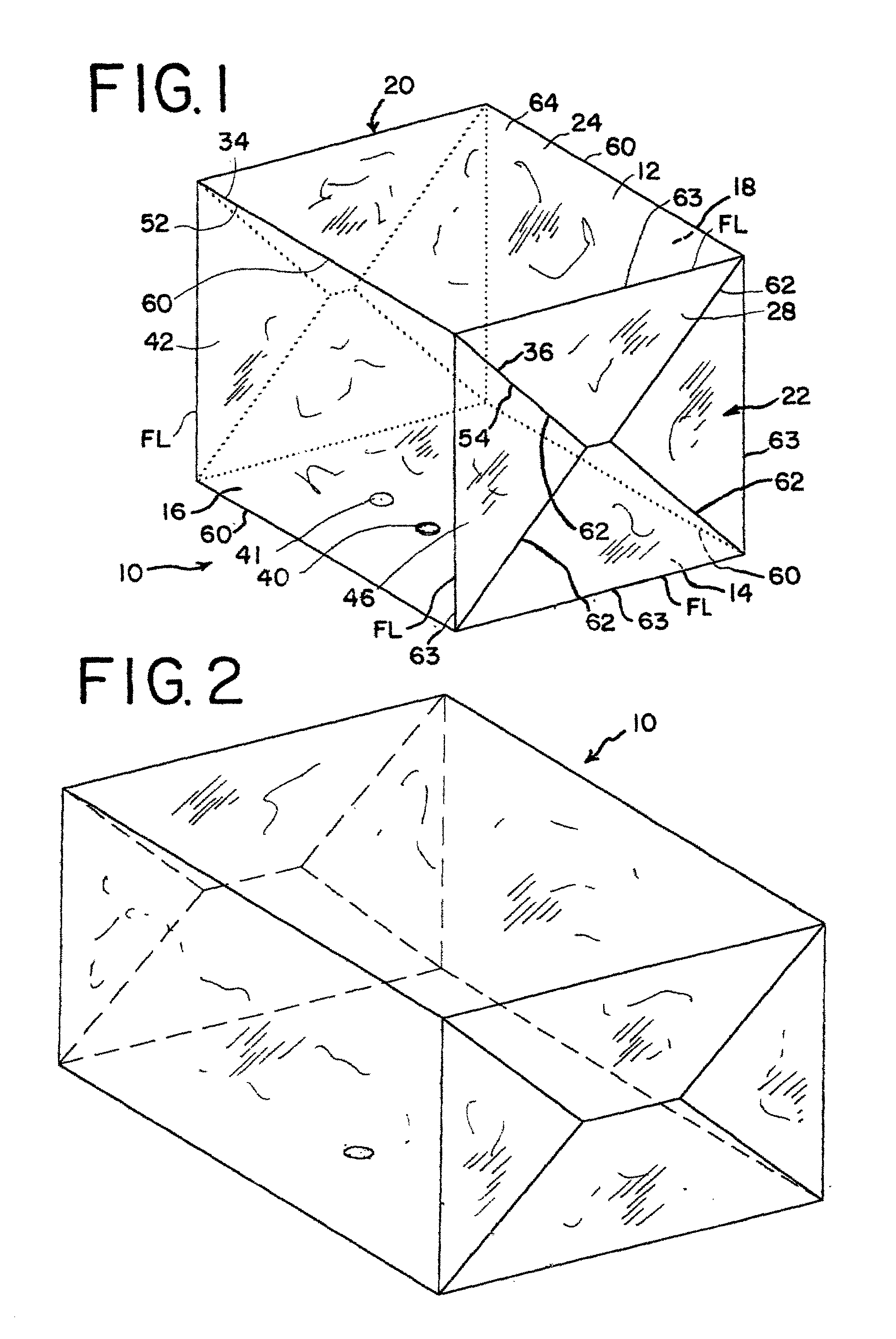
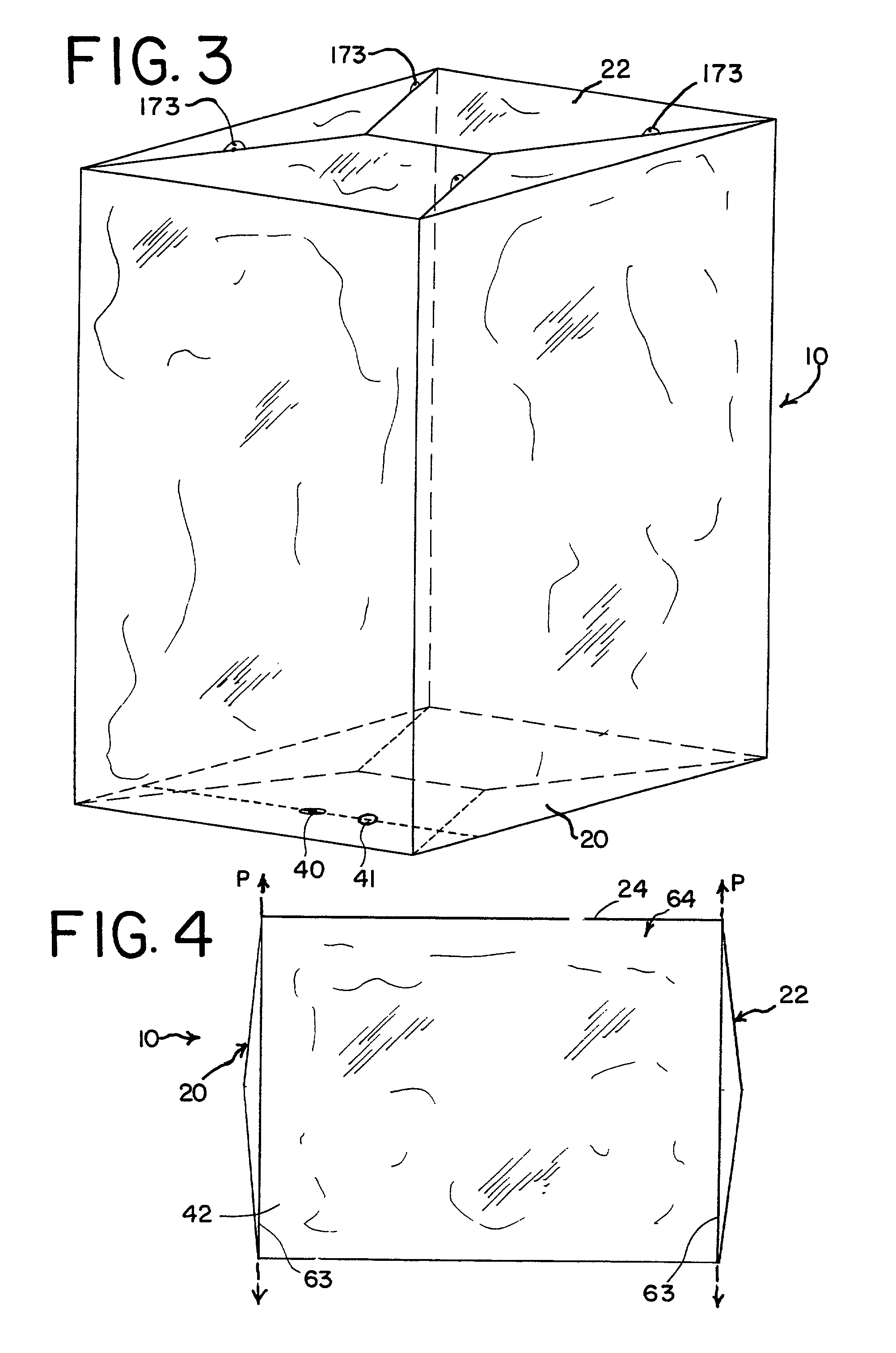
[0054]Referring to the drawings, FIG. 1 shows a container made in accordance with the present invention generally referred to with the reference numeral 10. The container 10 is a three-dimensional container capable of holding large amounts of fluid. The container 10 shown in FIG. 1 holds approximately 200 liters of fluid. The container 10, however, can be made in a variety of sizes. For example, FIG. 2 shows a container 10 sized to hold approximately 500 liters of fluid, and FIG. 3 shows a container 10 sized to hold approximately 1500 liters of fluid. The container 10 has a un...


PUM


Abstract

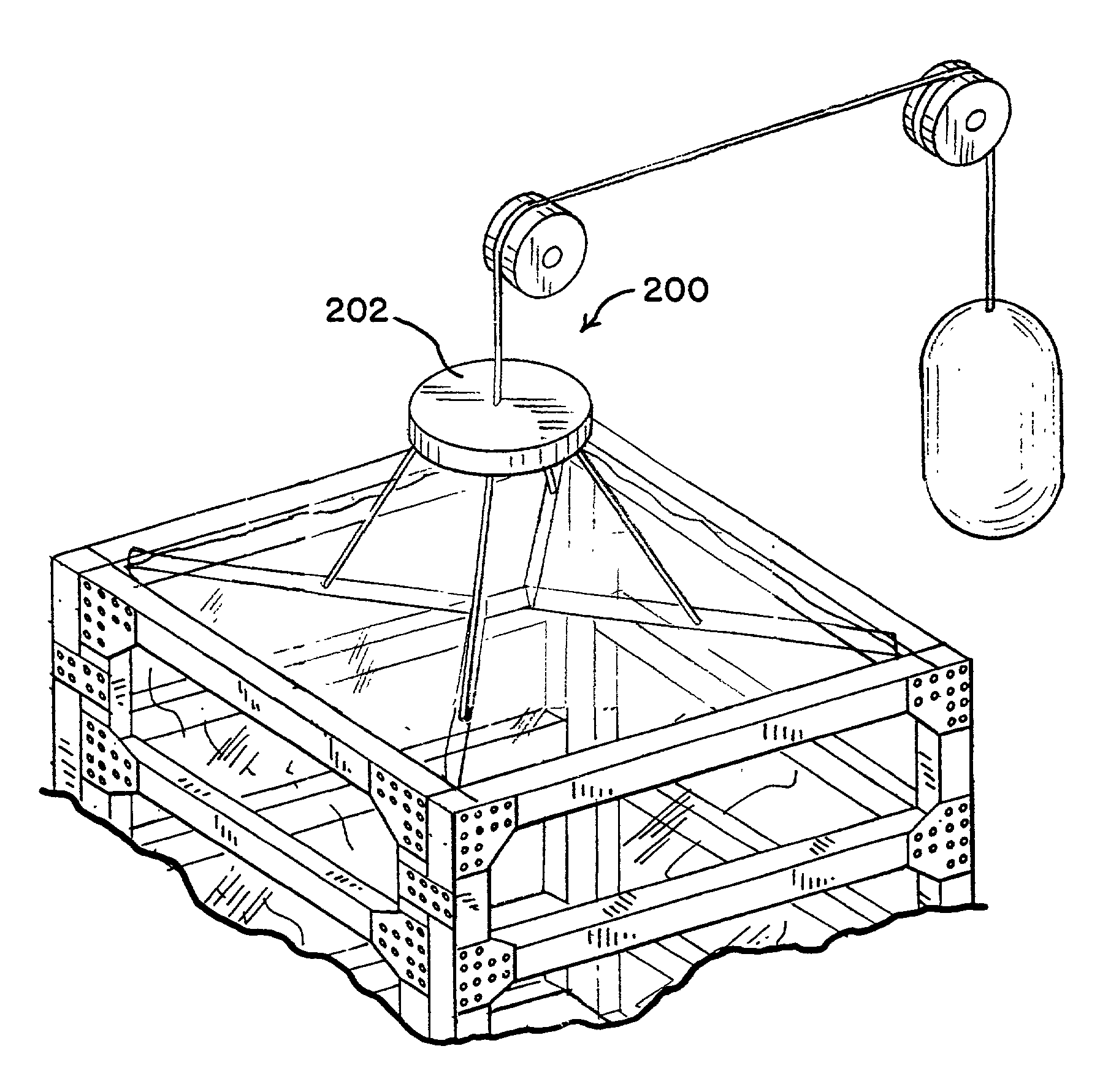
A container (10) having a plurality of panels (12–18) joined together to form a sleeve (64). The panels (12–18) each have an end edge that cooperate to define an imaginary plane (P) at one end of the sleeve (64). The container (10) further has an end panel (20,22) connected to the panels (12–18) at the one end of the sleeve (64). The end panel (20,22) has at least one portion extending beyond the imaginary plane (P). The supporting box (100) is provided to support the container (10). A hanger system (150) is provided and is attached to the box (100). The hanger system (150) supports an upper portion of the container (10) within the box (100). The container (10) is also provided with a port closure (300) that provides both a sterile and gas permeable barrier.

Description

DESCRIPTION[0001]1. Technical Field[0002]The present invention relates, in general, to flexible containers and, more specifically, to large volume, three-dimensional flexible containers.[0003]2. Background of the Invention[0004]Containers used for the shipping, storing, and delivery of liquids, such as therapeutic fluids or fluids used in other medical applications, are often fabricated from single-ply or multi-ply polymeric materials. The materials are typically in sheet form. Two sheets of these materials are placed in overlapping relation, and the overlapping sheets are bonded at their peripheries to define a chamber or pouch for containing the fluids. These types of bags are typically referred to as two-dimensional flexible containers, flat bags, or “pillow bags.” U.S. Pat. No. 4,968,624 issued to Bacehowski et al. and commonly assigned to the assignee of the present application, Baxter International Inc. (“Bacehowski”), discloses a large volume, two-dimensional flexible contain...

Claims


Application Information

Patent Timeline
Patent Type & Authority Patents(United States)
IPC IPC(8): A47H1/10A61J1/16A61J1/10B65B69/00B65D90/20
CPCB65B69/0091B65D90/205B65D77/061
Inventor HURST, WILLIAM S.SMITH, SIDNEY T.CALOZ, PIERRERAMACHANDRAN, SINDHUULM, MICHELE M.RODRIGUEZ, JESSE F.
Owner BAXALTA GMBH
Learn More