Concentrated buoyancy subsea pipeline apparatus and method

a technology of buoyancy and pipelines, applied in mechanical equipment, pipe laying and repair, pipe supports, etc., can solve the problems of pipelines crossing the ocean bottom to bend sharply, dangerous topographic features that can compromise pipelines and subsea structures, and complex topography

Active Publication Date: 2006-04-11
KELLOGG BROWN & ROOT INC
View PDF18 Cites 20 Cited by
  • Summary
  • Abstract
  • Description
  • Claims
  • Application Information

AI Technical Summary

Problems solved by technology

Far off the coast, unlike relatively featureless continental shelves where most offshore oil and gas has been historically developed, the deep-water ocean bottom has hazardous topographic features that can compromise pipelines and subsea structures.
This complex topography is a significant challenge to laying subsea pipelines across these regions.
The abrupt changes in the slope across such topographic features and escarpments can cause pipelines crossing them to bend sharply.
This bending leads to ovalization of the pipeline cross section which may cause the pipeline to buckle and collapse.
Long free spans exceeding the stress and vortex induced vibration fatigue limits of the pipeline can also result from seabed irregularities associated with these topographic features.
Many issues arise with respect to the laying of subsea pipelines including countering the subsea currents, traversing the varying topography, and the complexity of the installation process itself.
Existing solutions for spanning the treacherous topographic features described above can be too costly, risky, environmentally destructive, or result in other hazards.
The re-routing option can be time consuming and expensive because it requires a longer pipeline.
The trenching, blasting and drilling options can have a negative impact on the undersea environment and sea life and can likewise be very costly.
Other options, including the installation of rigid pilings and framework to support pipeline spans have been tried on smaller scale installations, but would be very costly on longer spans.
The hazardous topography of the continental slopes increases the risk (through stresses and failures) that leaks may occur.

Method used


Image

  • Concentrated buoyancy subsea pipeline apparatus and method
  • Concentrated buoyancy subsea pipeline apparatus and method
  • Concentrated buoyancy subsea pipeline apparatus and method

Examples


Embodiment Construction

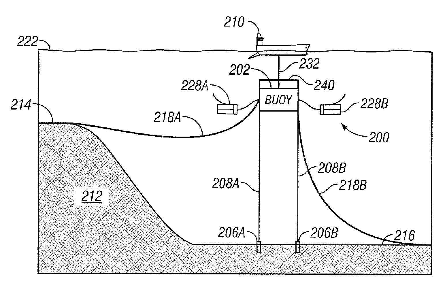
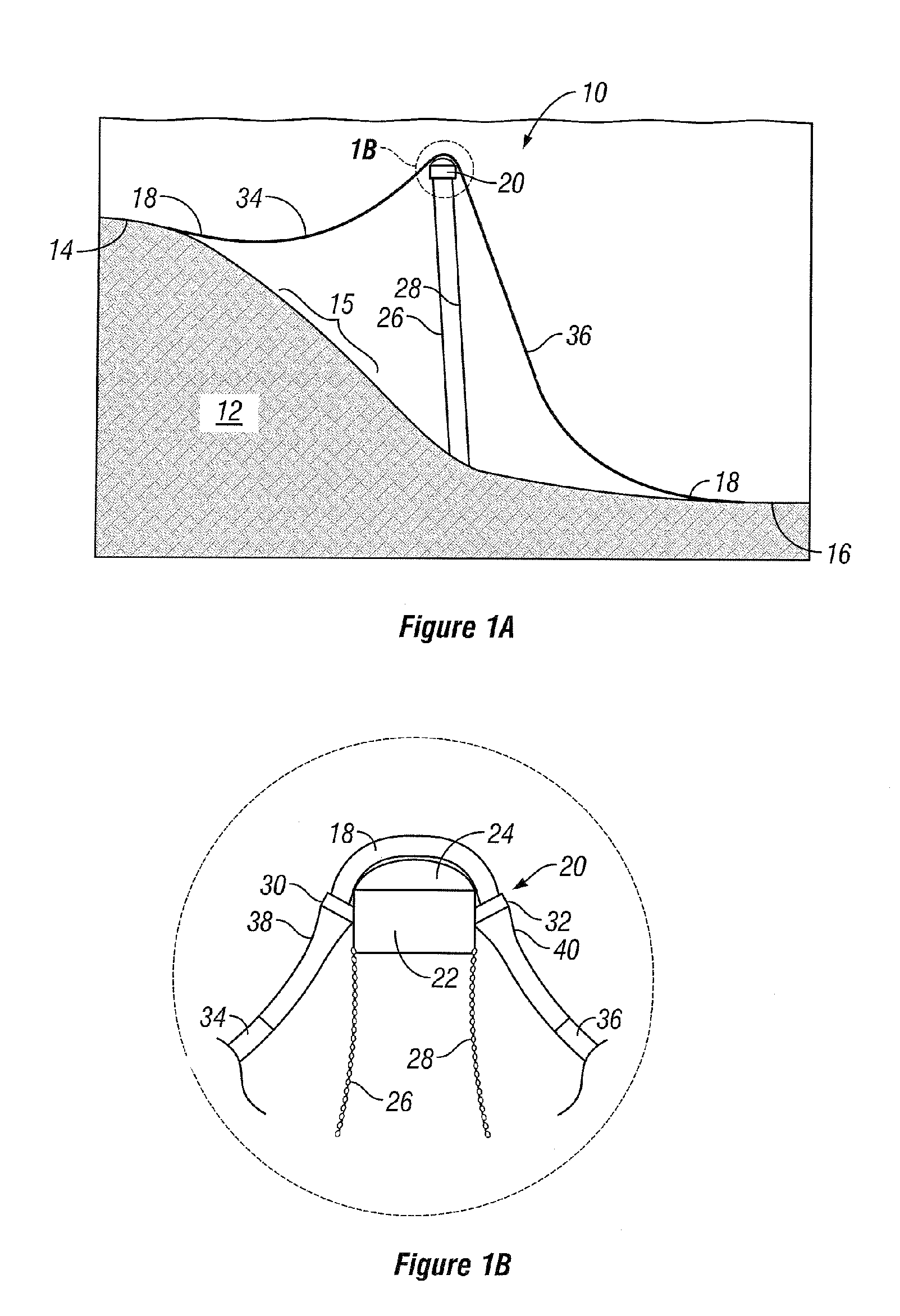
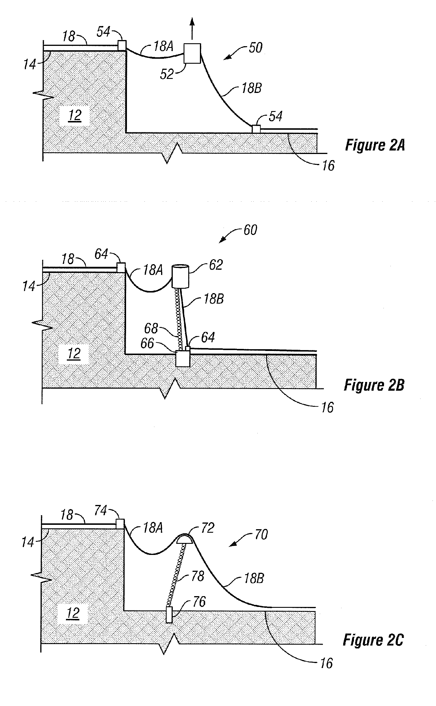
[0020]Referring initially to FIGS. 1A and 1B together, a schematic of a concentrated buoyancy pipeline system 10 is shown. System 10 is shown traversing an undersea scarp 12 and extends from the top 14 of scarp 12, across a slope 15, to a bottom 16 of scarp 12. System 10 includes a length of pipeline 18 in a bell-shaped configuration as it traverses scarp 12. While a scarp 12 is shown, it should be understood to one of ordinary skill in the art that various other topographic obstructions and hazards including, but not limited to, basins, domes, valleys, cliffs, and canyons, may be traversed without departing from the spirit of the invention.

[0021]To traverse scarp 12, a concentrated buoyancy assembly 20 is located approximately mid-span along pipeline 18 to make it positively buoyant. Buoyancy assembly 20 desirably includes a buoyancy device 22, a profiled surface 24, and one or more tethers or mooring lines 26, 28 to secure concentrated buoyancy assembly 20 in place. Optionally, pi...


PUM


Abstract

Various apparatuses and methods to traverse an undersea topographic feature (12) with a subsea pipeline (18) are disclosed. The apparatuses and methods of the present invention accomplish this task through the use of a concentrated buoyancy scheme (10). The invention disclosed can allow more efficient and cost effective traversal of hostile terrain for subsea pipelines at great depths while minimizing the risk of rupturing the pipeline (18) or negatively impacting the surrounding undersea environment.

Description

BACKGROUND OF THE INVENTION[0001]The pursuit of petroleum products in deep waters has revealed an underwater world completely different from a level or gradually sloping seabed. Far off the coast, unlike relatively featureless continental shelves where most offshore oil and gas has been historically developed, the deep-water ocean bottom has hazardous topographic features that can compromise pipelines and subsea structures. These topographic features include enormous basins, domes, valleys, cliffs, canyons, and escarpments.[0002]An escarpment, or scarp, is a steep slope or cliff formed by erosion or faulting. The Sigsbee Escarpment, for example, is the largest in the Gulf of Mexico and lies beyond the edge of the continental shelf thousands of feet below the sea surface. The Sigsbee Escarpment encompasses drops of hundreds to over a thousand feet and extends for hundreds of miles. Between the Sigsbee Escarpment and the continental shelf exists a region called the continental slope. ...

Claims


Application Information

Patent Timeline
Patent Type & Authority Patents(United States)
IPC IPC(8): F16L1/12
CPCF16L1/20F16L1/14
Inventor MUNGALL, JOHN CHRISTIAN HARTLEYJOSHI, KHAMIR GIRISHLAMISON, CRAIG WONDER
Owner KELLOGG BROWN & ROOT INC
Why Eureka
Try Eureka