
Radiation image formation system

a technology of radiographic image and formation system, which is applied in the direction of patient positioning for diagnostics, instruments, applications, etc., can solve the problems that the image to be output cannot be reduced in life size and the image in life size cannot be obtained

Inactive Publication Date: 2006-04-11
KONICA MINOLTA INC
View PDF1 Cites 13 Cited by
  • Summary
  • Abstract
  • Description
  • Claims
  • Application Information

AI Technical Summary

Benefits of technology

The present invention provides a radiation image formation system that can reduce a magnified image to life size and output it through an image output apparatus. The system includes a radiation image radiographing apparatus, an image process apparatus, and an image output apparatus. The system sets a magnifying rate that satisfies the input pixel size and the minimum output pixel size. The image process apparatus reduces the image at a reducing rate of 1 / M, where M is the magnifying rate. The system can also inform the user of any errors that may occur during the process. Overall, the system allows for the efficient and accurate output of a life-size image.

Problems solved by technology

In this case, since a reducing rate is limited by the minimum output pixel size, an image to be output cannot be reduced in life size.
However, an image in life size cannot be obtained when radiography is performed at the magnifying rate of 4.

Method used


Image

  • Radiation image formation system
  • Radiation image formation system
  • Radiation image formation system

Examples


first embodiment

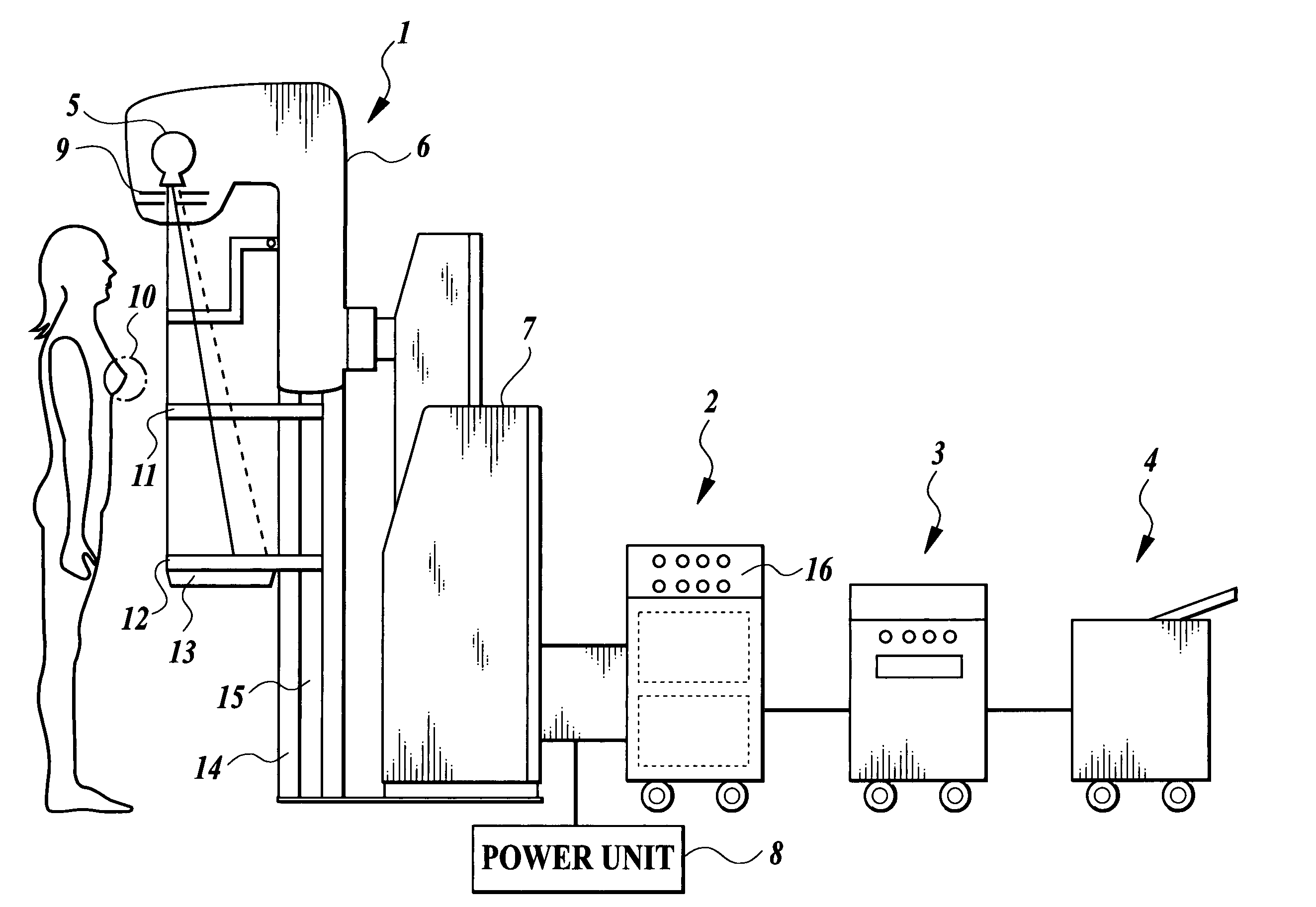
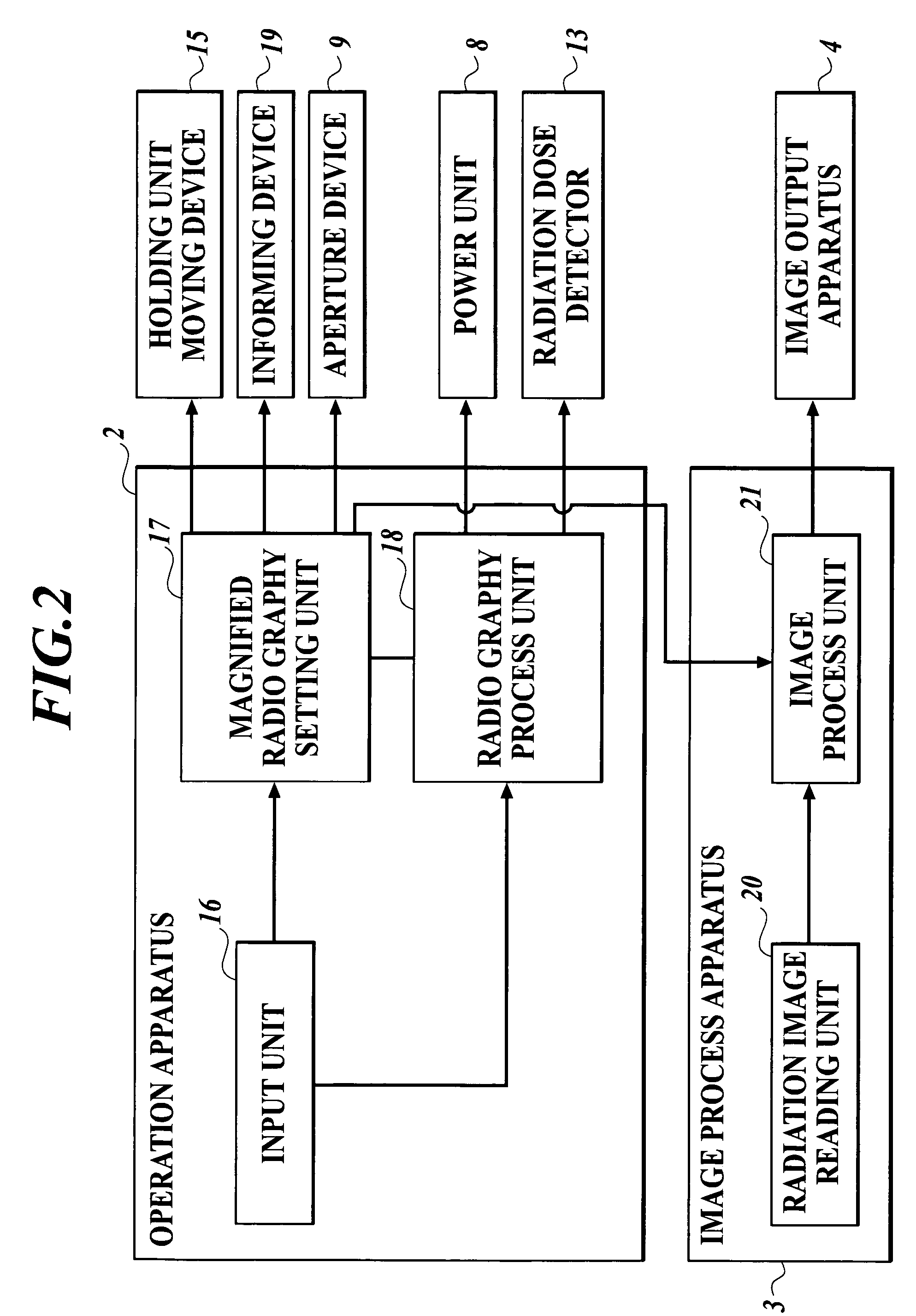
[0054]A radiation image formation system according to the first embodiment of the present invention is used for forming a radiation image of a mamma. As shown in FIG. 1, such a radiation image formation system comprises a mammography apparatus 1 for radiographing a radiation image of a mamma, an operation apparatus 2 for performing operation regarding the radiography of a radiation image, an image process apparatus 3 for processing to convert a radiation image radiographed into digital image data, and an image output apparatus 4 for recording image data on a recording medium.

[0055]The mammography apparatus 1 comprises a body 6 in which a radiation source 5 is located. As shown in FIG. 1, the body 6 is supported by a supporting stand 7 so that the body 6 is capable of moving up and down. The radiation source 5 is connected to a power unit 8 for supplying electric power necessary for the radiation source 5 to emit radiation. At an irradiation gate of the radiation source 5, an apertur...

second embodiment

[0103]Next, a second embodiment of the present invention will be described. Here, components in the second embodiment having the same marks as those in the first embodiment have similar functions to the first embodiment.

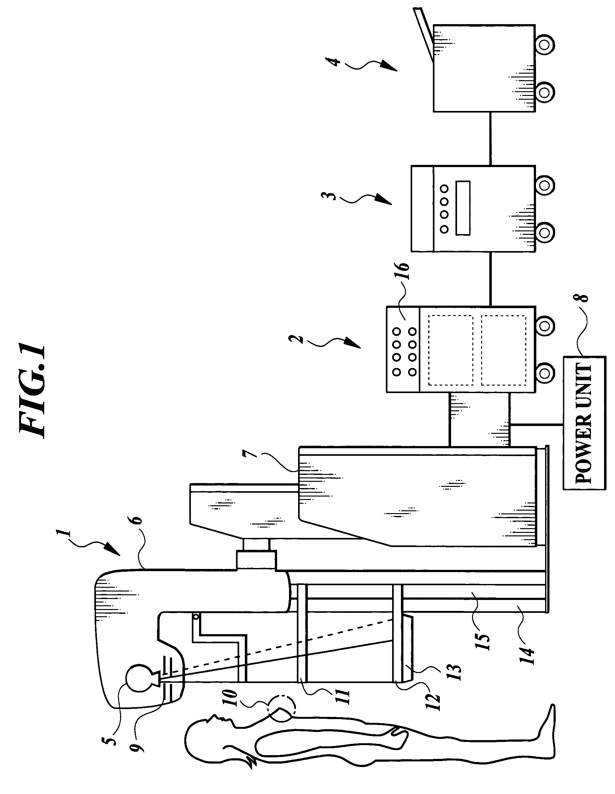
[0104]A radiation image formation system according to the second embodiment of the present invention is used for forming a radiation image of a chest or the like. As shown in FIG. 3, such a radiation image formation system comprises a radiation image radiographing apparatus 1 for radiographing a radiation image of a chest or the like, an operation apparatus 2 for performing operation regarding the radiographing of a radiation image, an image process apparatus 3 for converting a radiographed radiation image into digital image data and an image output apparatus 4 for recording image data on a recording medium.

[0105]The radiation image radiographing apparatus 1 comprises a body 6 in which a radiation source 5 is located. As shown in FIG. 3, the body 6 is supported by a ...


PUM

PropertyMeasurementUnit
distanceaaaaaaaaaa
distanceaaaaaaaaaa
sizeaaaaaaaaaa

Abstract

A radiation image formation system capable of reducing a magnified phase contrast image radiographed to life size and of outputting the reduced image at an output apparatus. The radiation image formation system has a magnified radiography setting unit for setting a magnifying rate M which satisfies:magnifying rate M≦input pixel size A / minimum output pixel size Bwhere the input pixel size A is a size of pixels composing a radiation image detected by a radiation image detector, and the minimum output pixel size B is a minimum size of pixels composing image data output by an image output apparatus, wherein a radiation image radiographing apparatus radiographs the radiation image at the magnifying rate M and an image process apparatus reduces the radiation image at the reducing rate 1 / M.

Description

BACKGROUND OF THE INVENTION[0001]1. Field of the Invention[0002]This invention relates to a radiation image formation system and, more particularly, to a radiation image formation system for reducing a magnified radiation image radiographed into life size and displaying the reduced radiation image.[0003]2. Description of the Related Art[0004]In recent years, a radiation image radiographing apparatus for radiographing a phase contrast image has been proposed. A phase contrast image is also called a refraction contrast image and used to be said that it could be obtained by radiographing with monochromatic parallel X-rays emitted from a synchrotron radiation X-ray source, such as Spring-8, or with a micro focus X-ray source having a focus size of about 10 μm. However, it has turned out that a phase contrast image can be obtained with a medical X-ray source (see Japanese Patent Application Publication (Laid-Open) No. 2001-91479). A phase contrast image is sharper and more high-resoluted...

Claims


Application Information

Patent Timeline
Patent Type & Authority Patents(United States)
IPC IPC(8): G01N23/04A61B6/00
CPCA61B6/04A61B6/4216A61B6/484A61B6/588A61B6/4452A61B6/545A61B6/502A61B6/4092
Inventor OHARA, HIROMU
Owner KONICA MINOLTA INC
Learn More