Kitchen appliance with a safety interlock

a technology of safety interlocking and kitchen appliances, which is applied in the direction of threshers, grain treatment, manufacturing tools, etc., can solve the problems of occupying a relatively large amount of counter space and complicating the construction of the bowl

Inactive Publication Date: 2006-04-18
HAMILTON BEACH BRANDS
View PDF51 Cites 55 Cited by
  • Summary
  • Abstract
  • Description
  • Claims
  • Application Information

AI Technical Summary

Benefits of technology

[0009]In yet another aspect, a preferred embodiment of the present application is directed to a kitchen appliance with a safety interlock for processing foodstuff. The kitchen appliance includes a housing and a motor mounted within the housing. The motor includes a drive shaft that extends out of the housing and at least one portion of the drive shaft is movable along a drive axis. A switch is mounted in the housing and a bowl is removably mountable to the housing such that the drive shaft extends into the bowl in a working position. A lid is removably mountable over a mouth of the bowl. One of the lid and bowl actuate the at least one portion of the drive shaft to close the switch such that power is able to be provided to the motor when the bowl is in the working position and the lid is mounted over the bowl.

Problems solved by technology

The side-by-side kitchen appliance also tends to take up a relatively large amount of counter space in a kitchen.
However, prior bowl over motor housing kitchen appliances require the additional movable shaft located in the bowl, which complicates construction of the bowl and requires the addition of the movable shaft adjacent a periphery of the bowl or within the handle of the bowl.

Method used


Image

  • Kitchen appliance with a safety interlock
  • Kitchen appliance with a safety interlock
  • Kitchen appliance with a safety interlock

Examples


Embodiment Construction

[0018]Certain terminology is used in the following description for convenience only and is not limiting. The words “right”, “left”, “lower” and “upper” designate directions in the drawings to which reference is made. The words “inwardly” and “outwardly” refer to directions toward and away from, respectively, the geometric center of the preferred kitchen appliance and designated parts thereof. The terminology includes the above-listed words, derivatives thereof and words of similar import.

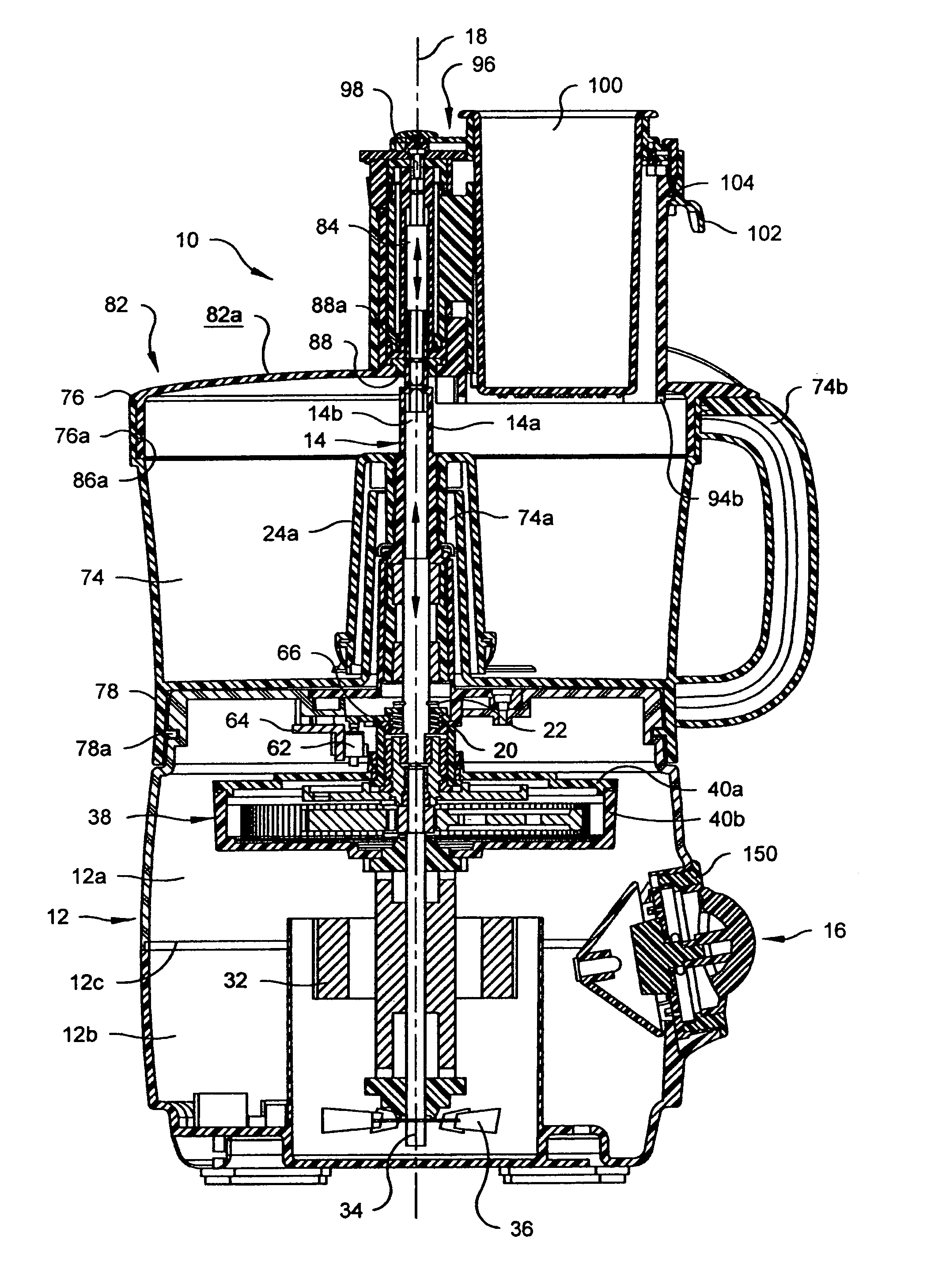
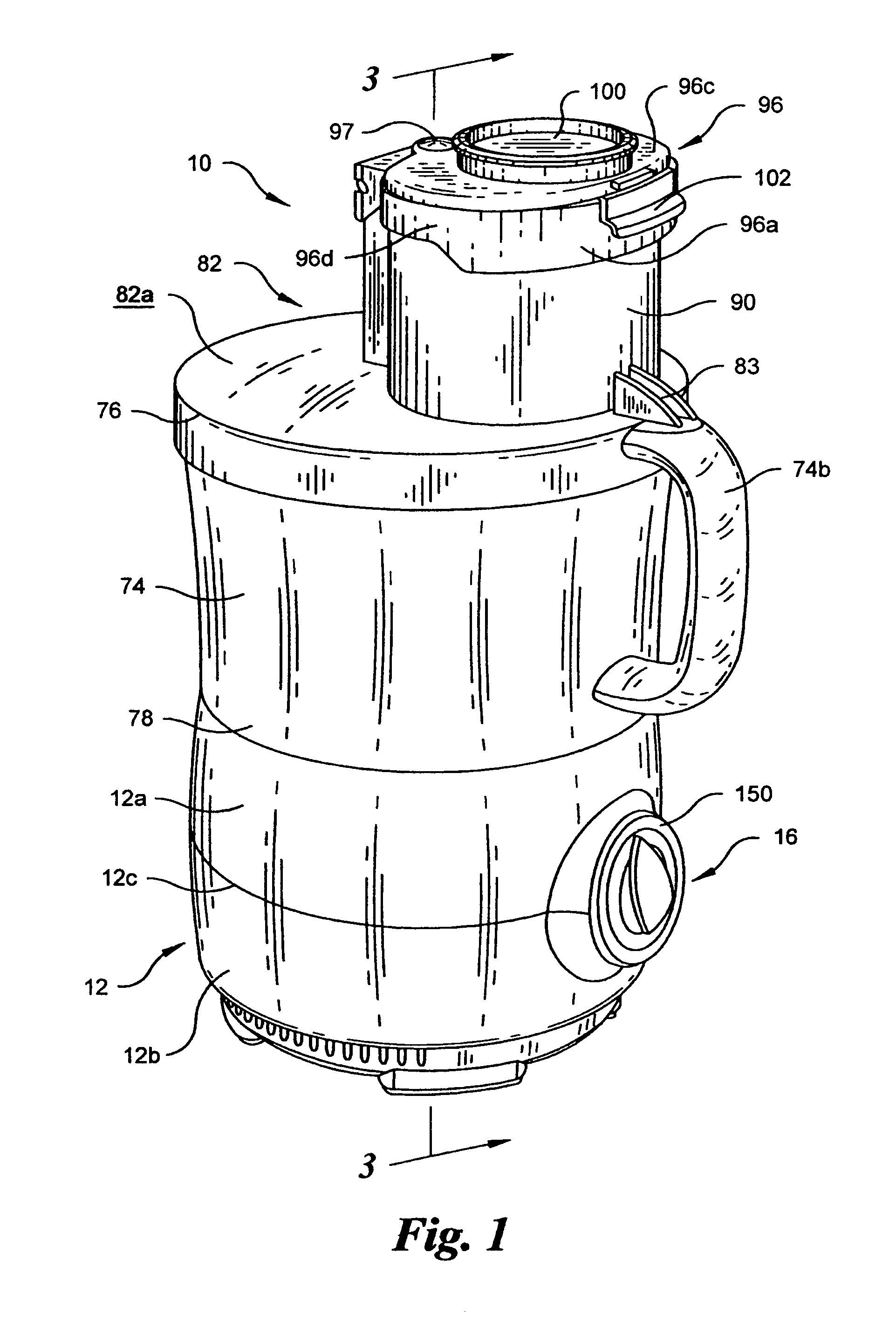
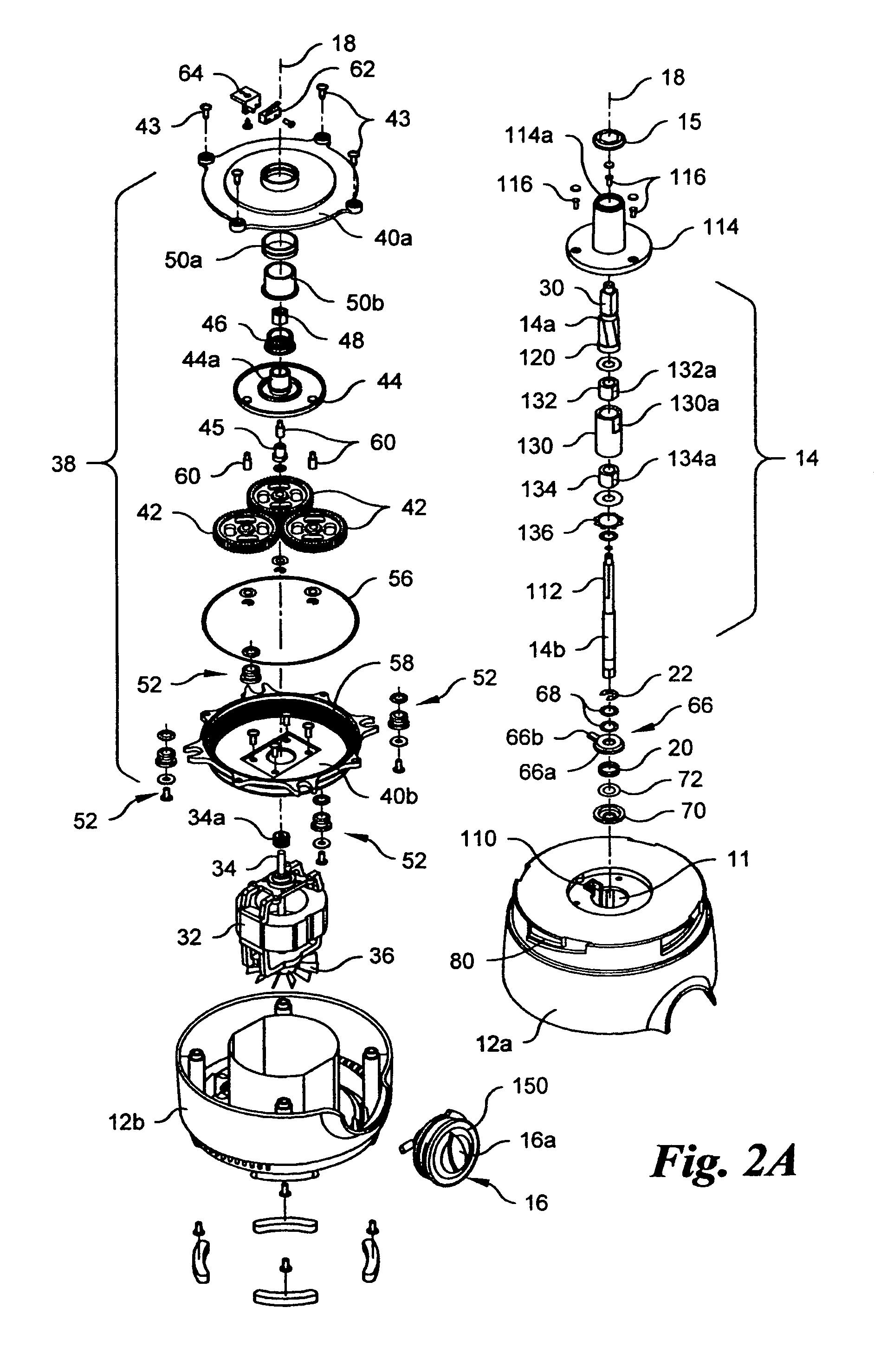
[0019]Referring to the drawings in detail, wherein like numerals indicate like elements throughout, there is shown in FIGS. 1–5, a preferred embodiment of a kitchen appliance 10 with a safety interlock for processing foodstuff, in accordance with the present application.

[0020]Referring to FIGS. 1, 2A and 3A, in the preferred embodiment, the kitchen appliance 10 of the present application includes a housing 12 with a drive shaft 14 extending therefrom. Preferably, the housing 12 has a generally cylin...


PUM


Abstract

A kitchen appliance with a safety interlock for processing foodstuff includes a housing with a drive shaft extending therefrom. The drive shaft is rotatable about a drive axis and at least one portion of the drive shaft is movable along the drive axis between an extended position and a retracted position. A switch is supported in the housing and a bowl is removably mountable to the housing. The bowl includes a mouth and the drive shaft extends into the bowl when the bowl is secured to the housing in a working position. A bowl lid is removable mountable over the mouth of the bowl. The bowl lid is in a working position when it is mounted over the bowl when the bowl is in the working position. The bowl lid includes a lid shaft extending from the bowl lid that is in an operative relationship with the drive shaft when the bowl and bowl lid are in the working position. The lid shaft urges the at least one portion of the drive shaft into the retracted position when the lid shaft is in an operative position. The at least one portion of the drive shaft closes the switch in a retracted position such that power is able to be provided to the kitchen appliance.

Description

BACKGROUND OF THE INVENTION[0001]The present application is directed to a kitchen appliance with a safety interlock and, more particularly, to a safety interlock comprised of at least one portion of a drive shaft of the kitchen appliance that is movable.[0002]Kitchen appliances commonly include a motor housing with a motor positioned therein, a bowl that is removably mountable to the motor housing and a lid that is removably mountable over a mouth of the bowl. A drive shaft extends from the motor housing into the bowl when the bowl is mounted to the motor housing. The drive shaft is rotatably driven by the motor and a processing tool is removably securable to the drive shaft for processing foodstuff within the bowl. During operation, a number of safety interlocks have been developed that prevent a user's hands from coming into contact with the processing or cutting tool when the bowl is mounted to the housing and the bowl lid is mounted to the bowl.[0003]Prior safety interlocks may ...

Claims


Application Information

Patent Timeline
Patent Type & Authority Patents(United States)
IPC IPC(8): B02C23/00B02C1/08B02C13/28B02C17/02A47J43/00A47J43/07A47J44/00B01F13/06F16P3/08H01H9/20
CPCF16P3/08A47J43/0777
Inventor CARNEVALE, FRANCESCO LEOPOLDO
Owner HAMILTON BEACH BRANDS
Why Eureka
Try Eureka