
Microchip ring trap for cold atoms or molecules

Inactive Publication Date: 2006-04-18
THE GOVERNMENT OF THE US SEC THE AIR FORCE
View PDF2 Cites 33 Cited by
  • Summary
  • Abstract
  • Description
  • Claims
  • Application Information

AI Technical Summary

Problems solved by technology

In general, these devices have been made in free space (i.e. the atoms are not trapped) and have very large power, space, and weight requirements.

Method used


Image

  • Microchip ring trap for cold atoms or molecules
  • Microchip ring trap for cold atoms or molecules
  • Microchip ring trap for cold atoms or molecules

Examples


Embodiment Construction

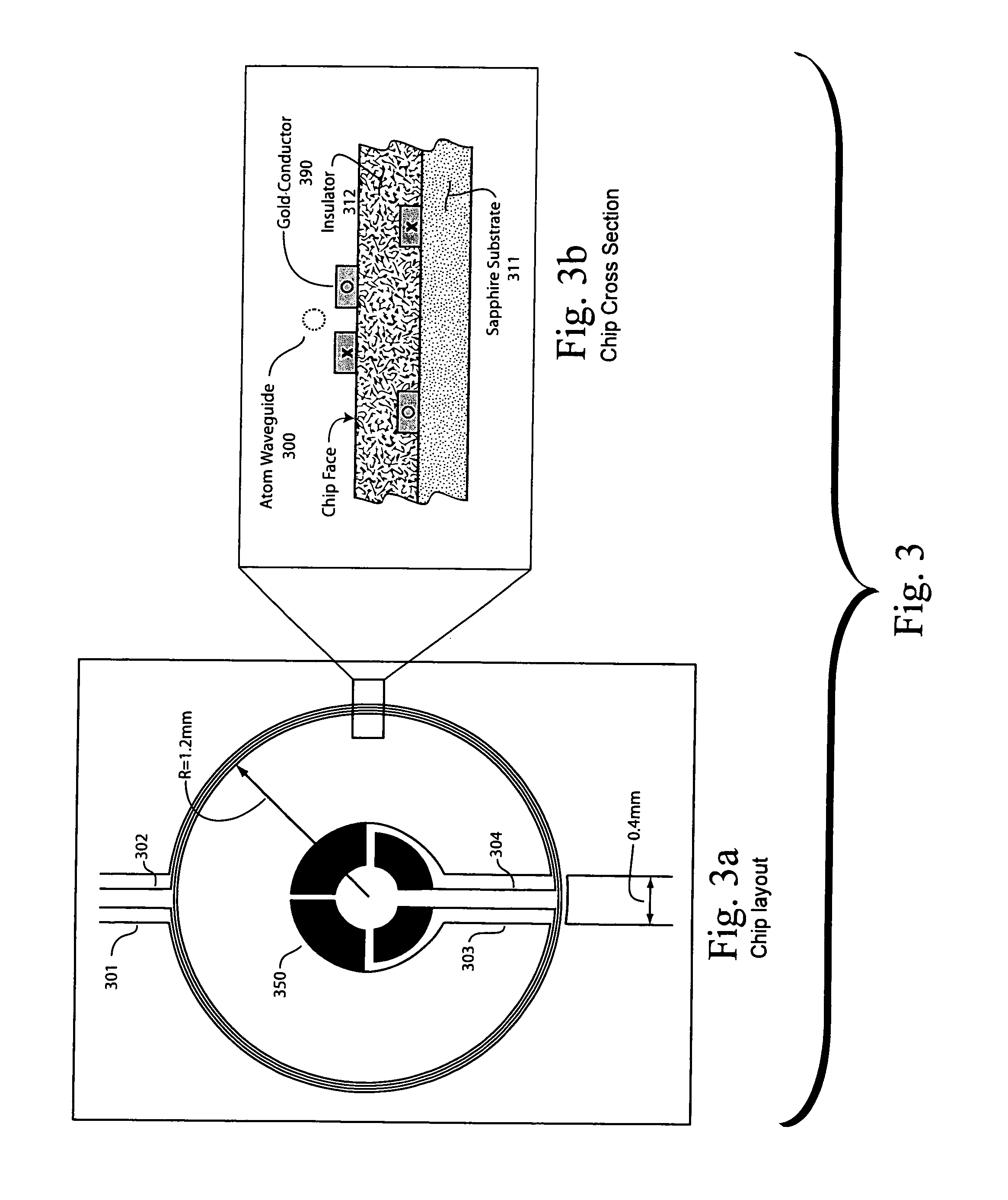
[0014]The present invention includes a symmetric circular magnetic waveguide for cold neutral atoms using current carrying wires on a microchip. This design is similar to Chapman et al PRL 2001 87.270401 but on a microchip. The waveguide is ideal to make an ultra-sensitive gyroscope using atom interferometry and the Sagnac effect. Either cold thermal atoms or quantum degenerate gasses (e.g. Bose-Einstein condensates, BECs) may be used. This technology can also be used in general inertial force sensing (accelerometers, gravimeters), atomic clocks, electromagnetic field sensing, and quantum computing.

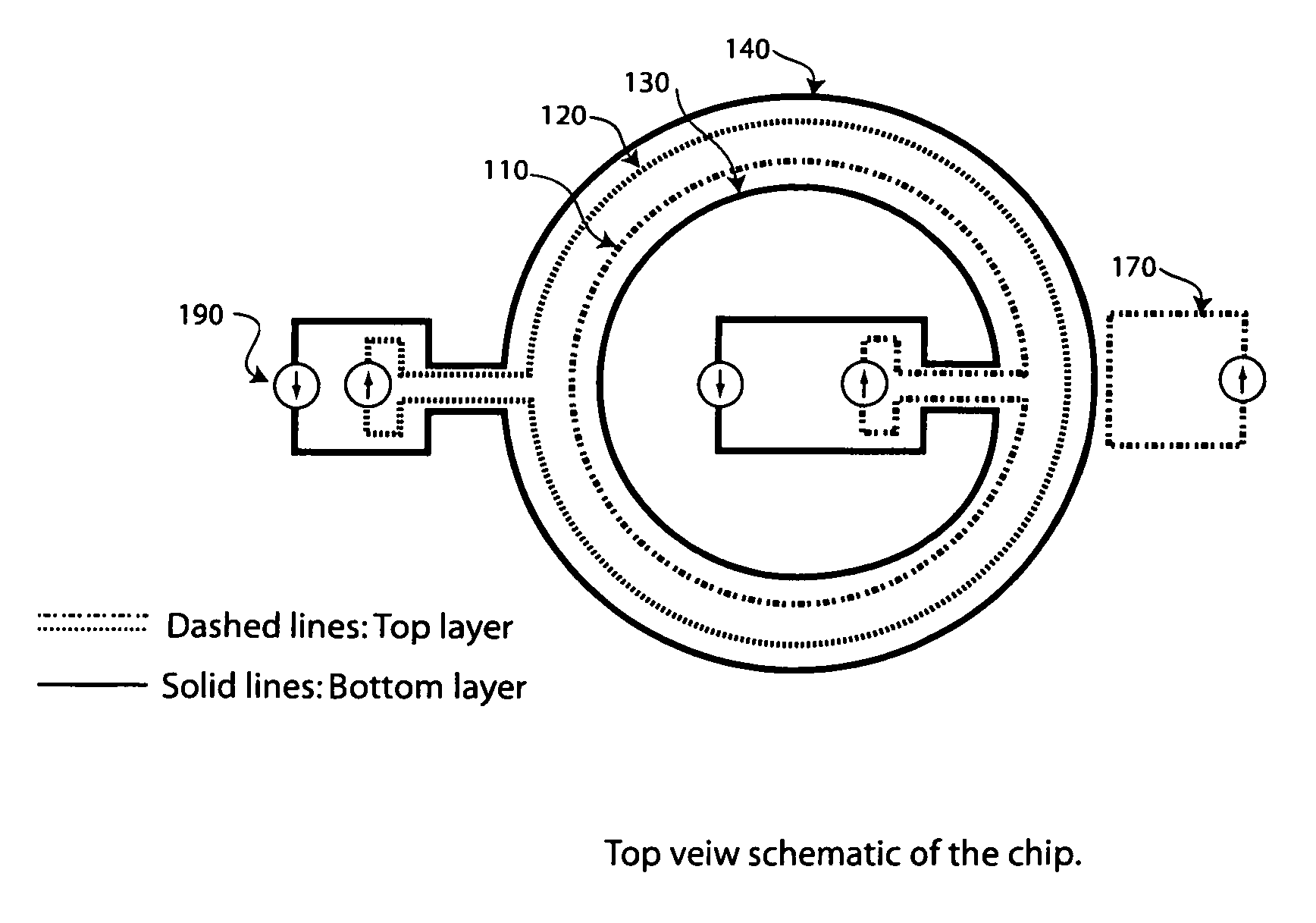
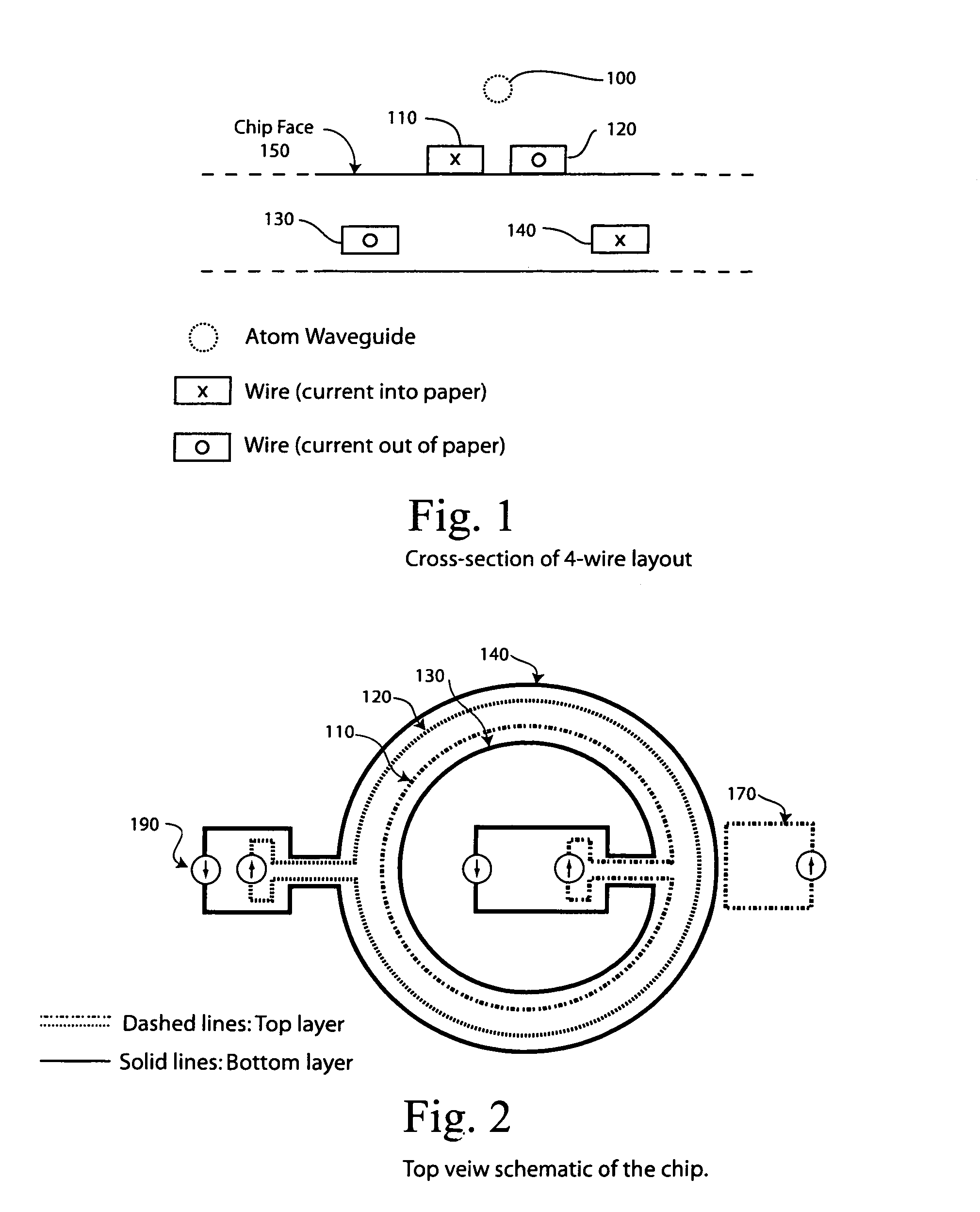
[0015]The invention consists of a particular multi-layer layout of wires on a microchip. These conductive wires may be produced by photolithography on a substrate (e.g. gold on sapphire). There are four wires crucial to the design, see FIG. 1 below, essentially a pair of “two-wire waveguides”. These wires are laid out on concentric circles with the inner and outer most wires on the lower ...


PUM


Abstract

A microchip ring trap for cold atoms or neutral molecules consists of a particular multi-layer layout of wires on a microchip. These conductive wires may be produced by photolithography on a substrate (e.g. gold on sapphire). There are four wires crucial to the design, essentially a pair of “two-wire waveguides”. These wires are laid out on concentric circles with the inner and outer most wires on lower level of the chip, and the middle pair of wires on the top layer (the chip surface).

Description

STATEMENT OF GOVERNMENT INTEREST[0001]The invention described herein may be manufactured and used by or for the Government for governmental purposes without the payment of any royalty thereon.BACKGROUND OF THE INVENTION[0002]The present invention relates generally to interferometry and more specifically to a symmetric circular magnetic waveguide for cold neutral atoms using current carrying wires on a microchip. The waveguide is ideal to make an ultra-sensitive gyroscope using atom interferometry and the Sagnac effect. Either cold thermal atoms, quantum degenerate gasses (e.g. Bose-Einstein condensates, BECs), or molecules with a magnetic dipole moment may be used. This technology can also be used in general inertial force sensing (accelerometers, gravimeters), atomic clocks, electromagnetic field sensing, and quantum computing.[0003]Important background to the present invention is found in the following U.S. patents of interest that are incorporated herein by reference are:[0004]U....

Claims


Application Information

Patent Timeline
IPC IPC(8): H05H3/00G01V7/04
CPCH05H3/04H05H3/02G01C19/64
Inventor CROOKSTON, MATTHEWROBINSON, MICHAELBAKER, PAUL
Owner THE GOVERNMENT OF THE US SEC THE AIR FORCE
Learn More