
Swing-type display device

a display device and swing-type technology, applied in the direction of static indicating devices, identification means, instruments, etc., can solve the problems of conventional swing-type display devices, display text characters or simple diagrams

Inactive Publication Date: 2006-04-18
NINTENDO CO LTD
View PDF25 Cites 16 Cited by
  • Summary
  • Abstract
  • Description
  • Claims
  • Application Information

AI Technical Summary

Benefits of technology

The patent text describes a swing-type display device that uses a linear array of light-emitting elements to display images. The device includes first and second light-emitting elements arranged in pairs, with each pair being activated for a predetermined period of time. The first and second light-emitting elements can be activated to emit light in different colors, allowing for the display of images in various colors. The device also includes a control section that activates the first and second light-emitting elements for a predetermined period of time, and a tilt sensor to detect the position of the device during swing. The control section can use PWM technique to drive the light-emitting elements, and an optical guide can be used to diffuse the light and make the displayed image less noticeable. The technical effects of this invention include the ability to display images in various colors and the reduction of stripes in the displayed image caused by the interspaces between the light-emitting elements.

Problems solved by technology

However, conventional swing-type display devices, which display images based on flickering red LEDs, can only display text characters or simple diagrams.
There is also a problem in that the displayed image may contain stripes associated with the interspaces between the red LEDs.

Method used


Image

  • Swing-type display device
  • Swing-type display device
  • Swing-type display device

Examples


first embodiment

[0042]A first embodiment of the present invention will be described. A major feature of the first embodiment is the ability to display multiple colors by employing two colors of LEDs and individually varying the luminance levels of the LEDs.

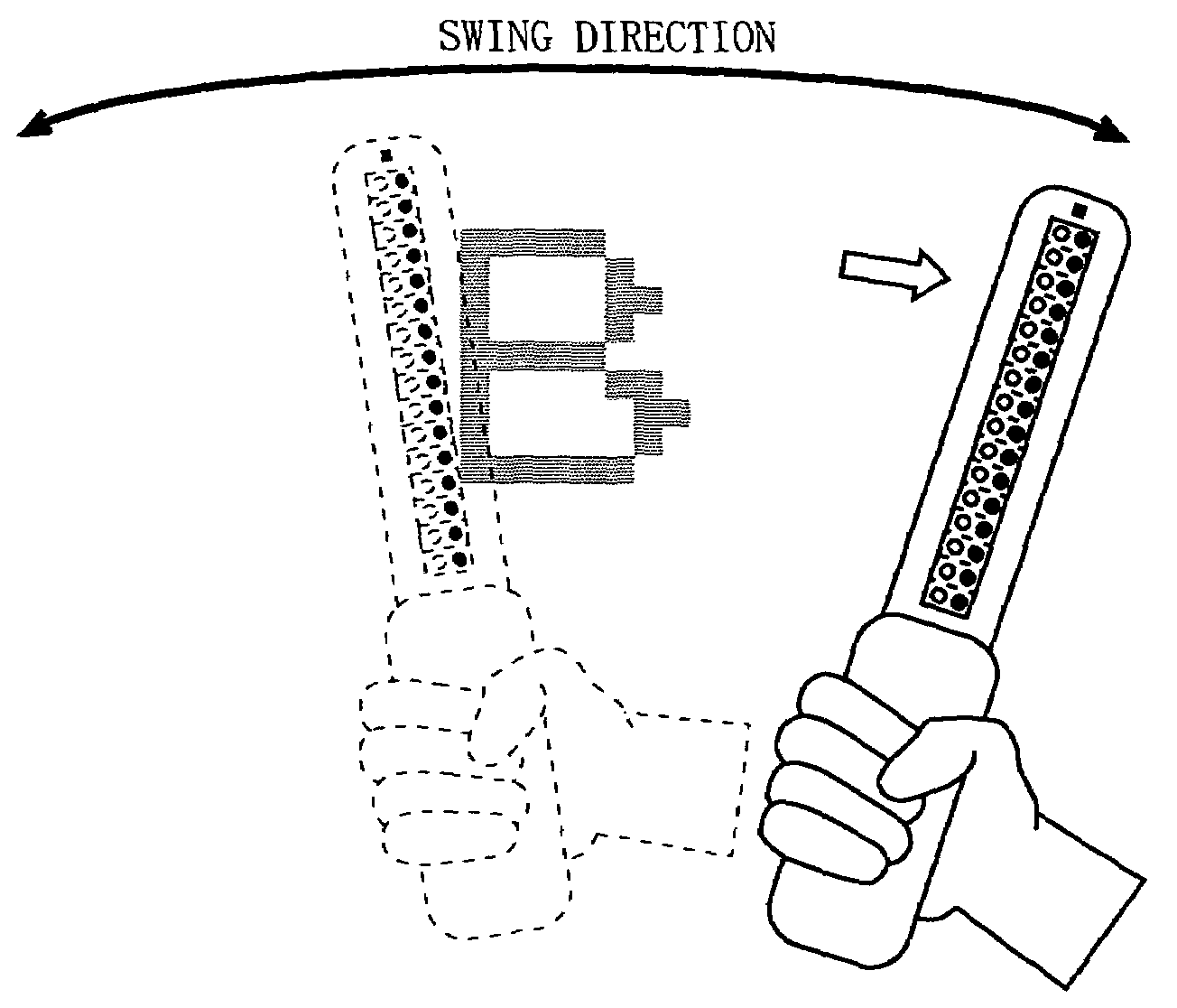
[0043]FIG. 1 is an external view showing a swing-type display device according to a first embodiment of the present invention. As shown in FIG. 1 the swing-type display device comprises sixteen red LEDs 10R, sixteen green LEDs 10G, an optical guide 20, a tilt sensor 30, and a grip portion 40. The red LEDs 10R are arranged in a linear array which is substantially perpendicular to a swing direction (i.e., a direction in which the swing-type display device is swung) shown in FIG. 1. The red LEDs and the green LEDs are grouped into pairs of two, such that each green LED 10G is located near a corresponding red LED 10R.

[0044]In the present embodiment, as shown in FIG. 1, the red LED 10R and the green LED 10G in each pair are located side by side along ...

second embodiment

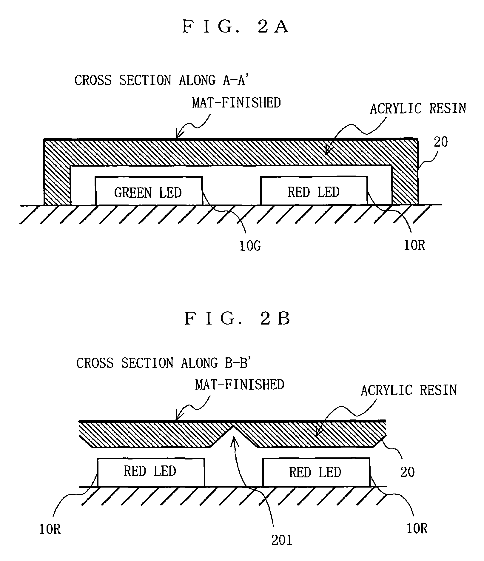
[0068]Next, a second embodiment of the present invention will be described. A major feature of the second embodiment is in that a plurality of partitions and a covering member are provided instead of the optical guide 20 according to the first embodiment, in order to make the stripes which may appear in the displayed image due to the interspaces between the LEDs less conspicuous.

[0069]FIG. 18 is an external view showing a swing-type display device according to the second embodiment of the present invention. As shown in FIG. 18, the swing-type display device comprises sixteen red LEDs 10R, sixteen green LEDs 10G, a covering member 70, a tilt sensor 30, and a grip portion 40. In FIG. 18, any constituent elements which also appear in FIG. 1 are denoted by like reference numerals, and the descriptions thereof are omitted.

[0070]The covering member 70 is composed of a light-transmitting material, e.g., acrylic resin, and is disposed so as to cover the light-emitting surfaces of the red LE...


PUM


Abstract

A linear array of red LEDs 10R is provided so as to extend in a direction substantially perpendicular to a direction in which a swing-type display device is swung, and a linear array of green LEDs 10G is further provided, the red LEDs 10R and green LEDs 10G being arranged in pairs of two. A CPU activates each of the red LEDs 10R and green LEDs 10G for a predetermined period to emit light in a luminance level in accordance with image data. As a result, an image corresponding to the image data is displayed in the trajectory of the swing due to persistence of vision. Thus, an image can be displayed in various colors.

Description

BACKGROUND[0001]1. Technical Field[0002]The illustrative embodiments relate to a swing-type display device, and more particularly to a swing-type display device incorporating a linear array of a plurality of light-emitting elements, such that each light-emitting element is activated for a predetermined period with a predetermined luminance level as the device itself is swung by a user, whereby an image is displayed in the trajectory of the swing due to persistence of vision.[0003]2. Description of Background Art[0004]Swing-type display devices incorporating an array of plurality of red LEDs (Light Emitting Diodes) are known. As the swing-type display device is swung, the red LEDs flicker with a predetermined pattern, whereby text characters (e.g., “STOP”) appear to be formed in the air due to persistence of vision.[0005]However, conventional swing-type display devices, which display images based on flickering red LEDs, can only display text characters or simple diagrams. There is al...

Claims


Application Information

Patent Timeline
Patent Type & Authority Patents(United States)
IPC IPC(8): H01L33/00G08B5/36G09G3/14G09G3/02G09F9/33G09F9/37G09G3/00H01L27/15
CPCG09G3/005G09F9/33
Inventor SHIMOMURA, MASARUISHIKAWA, MIKIHIROUEMURA, HIROTAKAFUKASAWA, RYOOTA, MASAHIKO
Owner NINTENDO CO LTD
Learn More