3D visual display system and method

a visual display and 3d technology, applied in the field of display technologies, can solve the problems of limited and achieve the effect of improving the size and shape of existing display screens

Inactive Publication Date: 2012-11-29
YU XIAO LIN
View PDF4 Cites 13 Cited by
  • Summary
  • Abstract
  • Description
  • Claims
  • Application Information

AI Technical Summary

Benefits of technology

[0004]One aspect of the present disclosure includes a three-dimensional (3D) display system. The 3D display system includes at least one 3D display element containing a series of element bases, and each element base includes a plurality of light-emitting elements in a predetermined arrangement. The 3D display system also includes a moving mechanism coupled to the 3D display element for causing the 3D display element to move along a predetermined direction. Further, the 3D display system includes a controller configured to control respective light-emitting conditions of the plurality of light-emitting elements contained in each element base, when each element base is moving in the predetermined direction, to create dynamic pixels based on persistence of vision so as to form a layer of 2D display. The layers of 2D display corresponding to the series of element bases overlap together to form a 3D display.

Problems solved by technology

The size and shape of an existing display screen is often limited by the current display technologies.

Method used


Image

  • 3D visual display system and method
  • 3D visual display system and method
  • 3D visual display system and method

Examples


Embodiment Construction

[0045]Reference will now be made in detail to exemplary embodiments of the invention, which are illustrated in the accompanying drawings. Wherever possible, the same reference numbers will be used throughout the drawings to refer to the same or like parts.

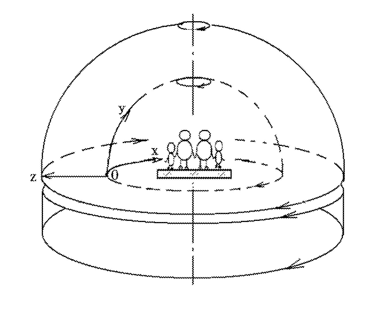
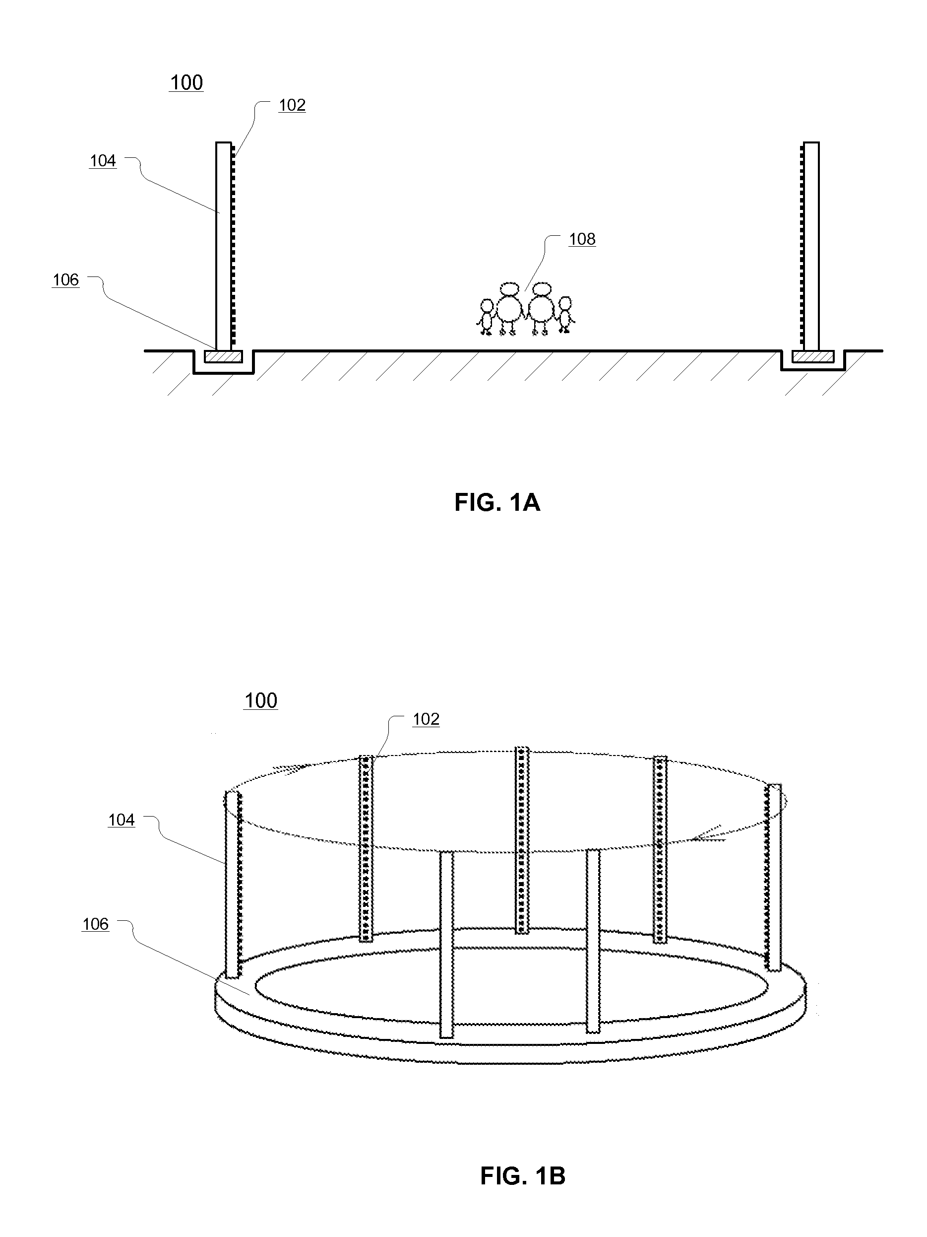
[0046]FIGS. 1A and 1B illustrate an exemplary display system 100 consistent with the disclosed embodiments. As shown in FIG. 1A, display system 100 includes a plurality of light-emitting elements 102, an element base 104, a circular rotating structure 106, and viewer(s) 108 (or view area 108). Other devices may also be included. For example, display system 100 may include a power source (not shown) for light-emitting elements 102, and may also include a driving mechanism (not shown) for driving circular rotating structure 106. In addition, display system 100 may include a controller (not shown) for controlling the various devices and / or display system 100.

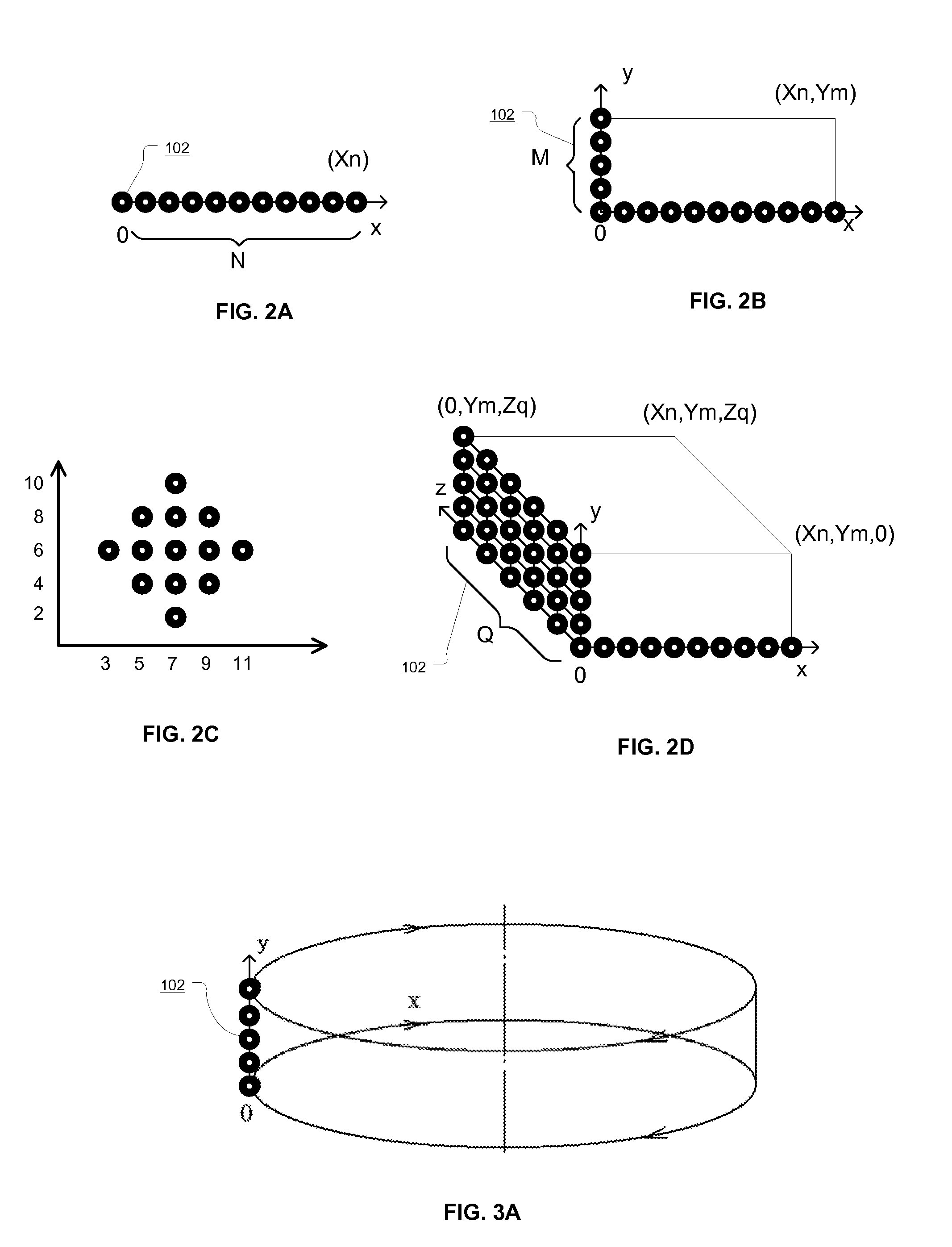
[0047]Light-emitting elements 102 are mounted on element base 104, which is f...


PUM


Abstract

A three-dimensional (3D) display system is provided. The 3D display system includes at least one 3D display element containing a series of element bases, and each element base includes a plurality of light-emitting elements in a predetermined arrangement. The 3D display system also includes a moving mechanism coupled to the 3D display element for causing the 3D display element to move along a predetermined direction. Further, the 3D display system includes a controller configured to control respective light-emitting conditions of the plurality of light-emitting elements contained in each element base, when each element base is moving in the predetermined direction, to create dynamic pixels based on persistence of vision so as to form a layer of 2D display. The layers of 2D display corresponding to the series of element bases overlap together to form a 3D display.

Description

FIELD OF THE INVENTION[0001]This application generally relates to display technologies and, more particularly, to visual systems with moving-pixel mechanisms.BACKGROUND[0002]Current displays often are based on liquid crystal display (LCD) or plasma display panel (PDP) technologies, or based on high-definition projection technologies. The size and shape of an existing display screen is often limited by the current display technologies. More specifically, for three-dimensional (3D) displays, current 3D images are based on two-dimensional (2D) images with parallax between a viewer's left eye and right eye. Thus, the third dimension (z-axis) is a virtual dimension and the viewer needs to wear stereoscopic glasses in order to view the 3D images. Therefore, there is need for display technologies that provide more flexible display mechanisms, both in 2D and 3D display.[0003]The disclosed methods and systems are directed to solve one or more problems set forth above and other problems.BRIEF...

Claims


Application Information

Patent Timeline
Patent Type & Authority Applications(United States)
IPC IPC(8): G02B27/22
CPCG02B27/2285G02B30/54
Inventor YU, XIAO LIN
Owner YU XIAO LIN
Why Eureka
Try Eureka