Display method and apparatus

a display method and display technology, applied in the direction of tyre sidewalls, visible signalling systems, tyre measurements, etc., can solve the problems of time-consuming to change the text message, time-consuming to change the pattern displayed, and high power requirements for strobe lights

Inactive Publication Date: 2005-05-19
TODOROV WILLIAM
View PDF15 Cites 13 Cited by
  • Summary
  • Abstract
  • Description
  • Claims
  • Application Information

AI Technical Summary

Problems solved by technology

There are a number of problems with this approach.
First, it is time-consuming to change the text message.
Further, strobe lights are expensive in terms of the power required to provide the illumination, and are also heavy, which is unacceptable in racing contexts.
However, in a more general sense, the above two problems remain with these prior art devices.
That is

Method used


Image

  • Display method and apparatus
  • Display method and apparatus
  • Display method and apparatus

Examples


Embodiment Construction

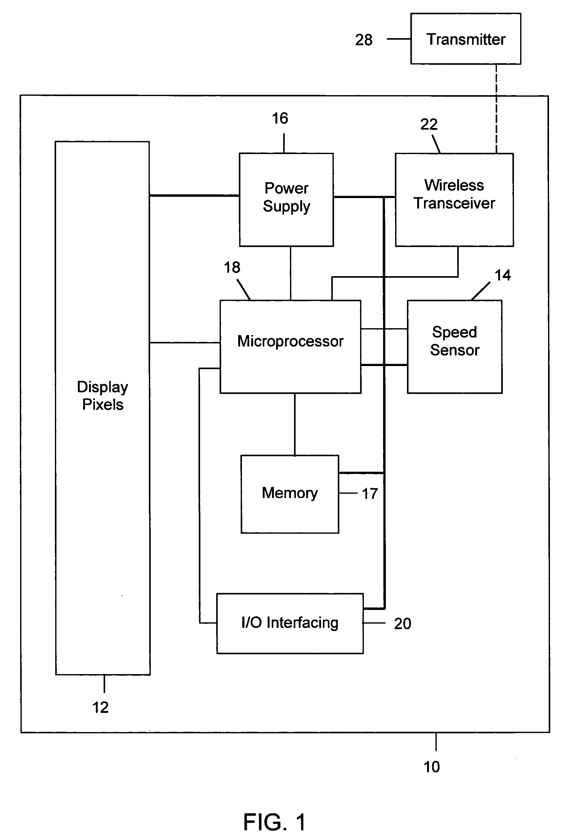
[0013] Referring to FIG. 1, there is illustrated in a block diagram, a display apparatus 10 in accordance with a preferred aspect of the present invention. The display apparatus includes an array of display pixels 12, a power supply 16, a microprocessor 18, and an input / output interfacing module 20. The microprocessor 18 may be driven by software stored on a memory 17. Optionally, the display apparatus 10 may include a speed sensor 14. Also optionally, the display apparatus 10 may include a wireless transceiver 22.

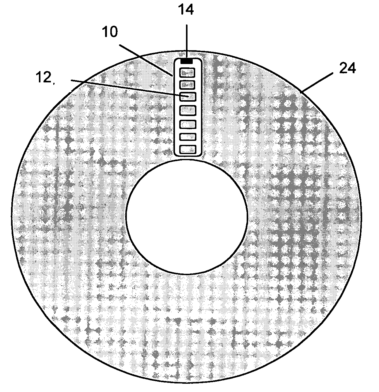
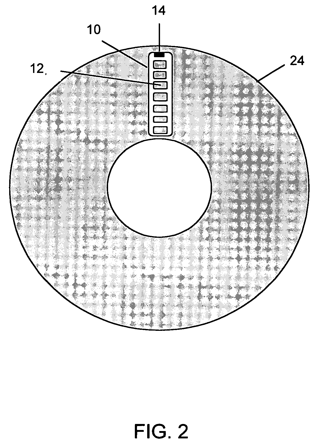
[0014] As illustrated in a side view of FIG. 2, and in the perspective view of FIG. 3, the display apparatus 10 is configured to be radially mounted on a tire 24. That is, as shown, the display apparatus 10 is disposed such that the longitudinal dimension of the array of display pixels is radially oriented on the tire. When mounted, the array of display pixels 12 flash on while in a readable position in the top arc of travel of the tire 24 to show text and / or graphics on ...


PUM


Abstract

A display apparatus is for mounting on a rotatable object. The display apparatus comprises: (a) a display array for displaying at least one display pattern; (b) a self-contained rotational speed sensor for sensing a rotational speed of the rotatable object, the self-contained rotational speed sensor being entirely mounted on the rotatable object; (c) a wireless receiver for receiving information from a signal source spaced from the rotatable object and, (d) a microprocessor for controlling the display array based on the rotational speed of the rotatable object to display the at least one display pattern using persistence of vision of a viewer.

Description

FIELD OF THE INVENTION [0001] The present invention relates generally to devices for displaying information or images, and more particularly relates to a display apparatus for producing a displayed image on the tire of a vehicle by timing the display of the image to correspond to a particular position of the wheel and relying on the persistence of vision of a viewer. BACKGROUND OF THE INVENTION [0002] Prior art technologies for displaying images on the wheels of vehicles have been developed. For example, U.S. patent application No. 20030042310 discloses a tire flasher display in which a text message is written directly on the tire. A strobe light is mounted for illuminating the tire. The frequency of the strobe light is correlated to the speed of the tire such that the text message is illuminated only in the same readable position during the rotation of the tire. As a result, the text message appears to remain stationary. [0003] There are a number of problems with this approach. Fir...

Claims


Application Information

Patent Timeline
IPC IPC(8): B60C13/00B60C19/00G08B3/00
CPCB60C19/00B60C13/001
Inventor TODOROV, WILLIAM
Owner TODOROV WILLIAM
Why Eureka
Try Eureka