In line fluid quality sensor

Active Publication Date: 2006-04-18
VITESCO TECH USA LLC
View PDF28 Cites 53 Cited by
  • Summary
  • Abstract
  • Description
  • Claims
  • Application Information

AI Technical Summary

Benefits of technology

[0007]The example sensor device can be inserted into a fluid supply line, for example. By having the sensor positioned in-line with an appropriate fluid passageway, the sensor is able to provide fluid quality information regarding substantially all of the fluid passing through the passageway. This is a

Problems solved by technology

One shortcoming of previously proposed devices is that they are typically limited to very specific applicatio

Method used


Image

  • In line fluid quality sensor
  • In line fluid quality sensor
  • In line fluid quality sensor

Examples


Example

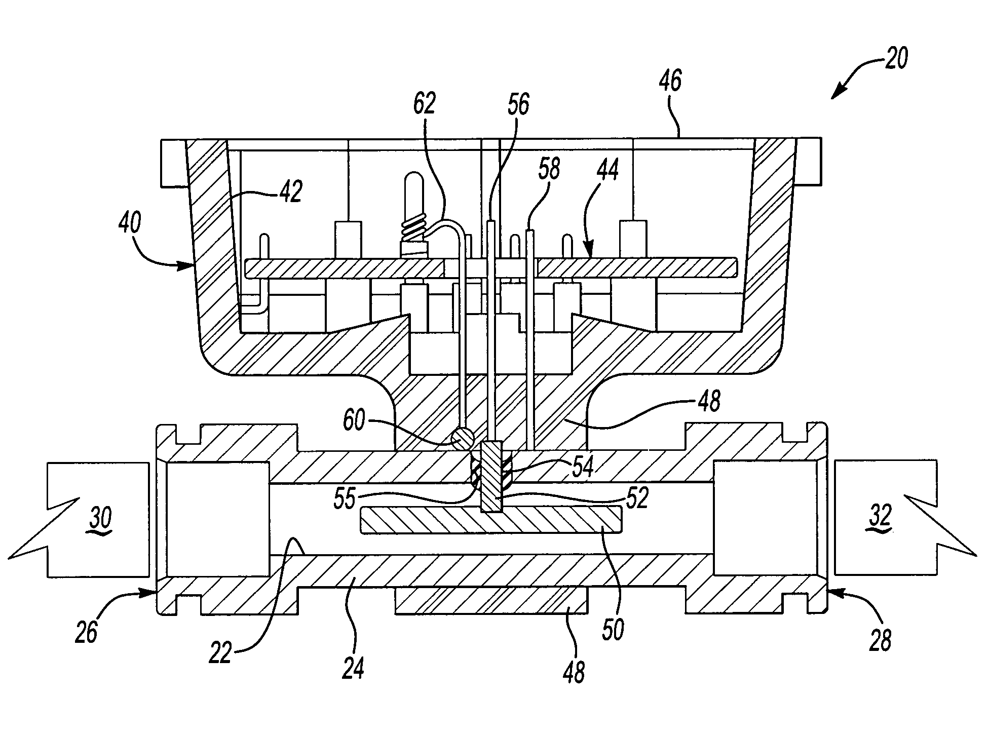
[0013]As can be appreciated from FIG. 1, a fluid quality sensor device 20 has a fluid passageway 22 through which a fluid of interest can flow. The fluid passageway 22 is formed through a first electrode 24. A first end 26 and a second end 28 of the first electrode 24 are adapted to be coupled with at least one fluid conduit 30. In the illustrated example, the first end 26 can be coupled with a first conduit 30 and the second end 28 can be coupled with a second conduit 32. In one example, the conduits 30 and 32 are sections of the same conduit.

[0014]By coupling the first electrode 24 with the conduits 30 and 32, the fluid passageway 22 accommodates fluid flowing through the conduits 30 and 32 and is in line with the conduits of an appropriate portion of a fluid handling system. In one example, the conduits 30 and 32 are fuel supply lines. In another example, the conduits 30 and 32 are a urea mixture supply for a catalytic converter arrangement.

[0015]The sensor device 20 includes a h...


PUM


Abstract

A fluid quality sensor (20) includes a first electrode (24) that has a fluid passageway (22) that is adapted to be placed in line with at least one fluid conduit (30). A housing (40) is supported on the first electrode (24) in one example by overmolding a portion (48) of the housing onto a portion of the first electrode (24). A second electrode (50) is supported within the fluid passageway (22) and electrically isolated from the first electrode (24). The first electrode (24) and the second electrode (50) operate as a capacitor for making fluid quality determinations.

Description

FIELD OF THE INVENTION[0001]This invention generally relates to a sensor for determining a fluid quality. More particularly, this invention relates to a sensor that can be placed in line along a fluid flow path for determining a quality of a fluid flowing along the path.DESCRIPTION OF THE RELATED ART[0002]Various fluid quality sensors are known. One type of determination made by such sensors is the concentration of one or more components within a fluid mixture. Some example sensors use a capacitor-based measurement technique to make a determination regarding the quality of interest.[0003]One example situation is in automotive fuel systems. It is useful, for example, to determine the alcohol content within a fuel mixture for purposes of adjusting fuel supply parameters in fuel injection systems. A known sensor for making such a determination is shown in U.S. Pat. No. 5,367,264. That document discloses a way of determining the alcohol content of a fuel mixture based on a capacitance a...

Claims


Application Information

Patent Timeline
IPC IPC(8): G01R27/26G01N33/26
CPCG01N33/26
Inventor STAHLMANN, DANIELMCKENZIE, ISABELLEWILDESON, RAY
Owner VITESCO TECH USA LLC
Why Eureka
Try Eureka