Two-way print apparatus and print method
a two-way print and print method technology, applied in the direction of printing, electrical equipment, spacing mechanisms, etc., can solve the problems of uneven color, more or less color difference, and not essential solutions, and achieve the effect of reducing the occurrence of uneven color
- Summary
- Abstract
- Description
- Claims
- Application Information
AI Technical Summary
Benefits of technology
Problems solved by technology
Method used
Image

Examples
embodiment 1
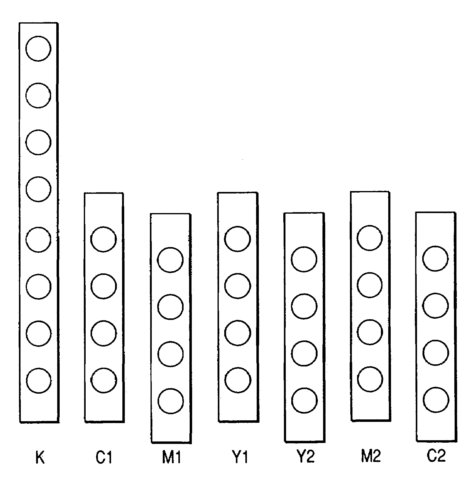
[0072]FIG. 3 is a schematic diagram to partially show the structure of the principal part of the recording head section in the head cartridge 1. In FIG. 3, numeral 100 designates a first recording head (hereinafter referred to as C1) for ejecting cyan ink. Numeral 101 denotes a first recording head (M1) for ejecting magenta ink. Numeral 102 is a first recording head (Y1) for ejecting yellow ink. Numeral 103 represents a second recording head (Y2) for ejecting yellow ink. Numeral 104 indicates a second recording head (M2) for ejecting magenta ink. Numeral 105 is a second recording head (C2) for ejecting cyan ink. Further, the head cartridge may also be provided with a recording head of Bk in addition to the above heads.
[0073]The group of these recording heads are incorporated to form the head cartridge 1. In the head cartridge 1, each of these recording heads has a plurality of ejection nozzles. For example, in the recording head 100 (C1), numeral 110 denotes cyan ejection nozzles. I...
embodiment 2
[0090]FIG. 8 is a schematic diagram to partially show the structure of the principal part used as another embodiment of the recording head section in the head cartridge 1. In FIG. 8, the components are similar to those of the recording head section of FIG. 3. However, the structure of the recording head section used in the present embodiment is different from that in FIG. 3 in that in each pair of recording heads of an identical color the recording heads as a pair constituting a pixel of each color are shifted from each other by half of the pitch of the nozzles in the recording heads in the sub-scanning direction.
[0091]In the above structure, FIG. 8 shows a case in which the primary color of cyan is printed. FIG. 8 shows a state in which two dots at the dot position 121 and at the dot position 122 are printed as a pair for the pixel 130. In the same figure the dot position 121 and the dot position 122 indicate positions of the dot ejected from the ejection nozzle 110 of the recordin...
embodiment 3
[0106]In Embodiments 1 and 2 described above, each pixel was constructed of a pair of two dots and at least one of identical color out of the ink materials was ejected in the symmetry ejection orders. Since each pixel is formed of a pair of two dots, these embodiments are suitable for print with enhancement of image density, for example, for print in which an image is formed on an OHP sheet.
[0107]In Embodiment 3, at least one of identical color out of the ink materials is ejected in the symmetric ejection orders, as in the above embodiments, in high-density regions, and different combinations of recording heads in the forward scan and in the backward scan are used in the symmetric recording head configuration ready for the two-way print in half-tone regions. This makes it feasible to express half tones in addition to the high-density regions in the two-way print.
[0108]It has been pointed out heretofore that when the so-called, horizontal heads arranged in the main scanning direction...
PUM
 Abstract
Description
Claims
Application Information
 - R&D Engineer
- R&D Manager
- IP Professional
- Industry Leading Data Capabilities
- Powerful AI technology
- Patent DNA Extraction
Browse by: Latest US Patents, China's latest patents, Technical Efficacy Thesaurus, Application Domain, Technology Topic.
© 2024 PatSnap. All rights reserved.Legal|Privacy policy|Modern Slavery Act Transparency Statement|Sitemap