Modular spinal fusion device

a spinal fusion device and module technology, applied in the field of surgical implants, can solve the problems of most common and perplexing, chronic low back pain, severe adverse societal effects, and low back pain

Inactive Publication Date: 2006-05-02
ZIMMER BIOMET SPINE INC
View PDF40 Cites 170 Cited by
  • Summary
  • Abstract
  • Description
  • Claims
  • Application Information

AI Technical Summary

Benefits of technology

[0009]The invention provides an implant for use in stabilization of one or more bones, for example, adjacent vertebrae. The implant includes two or more coupled structural elements. Each structural element includes a first

Problems solved by technology

Chronic low back pain is one of the most common and perplexing problems facing the field of orthopedic surgery.
In addition to patient discomfort, chron

Method used


Image

  • Modular spinal fusion device
  • Modular spinal fusion device
  • Modular spinal fusion device

Examples


Embodiment Construction

I. Overview:

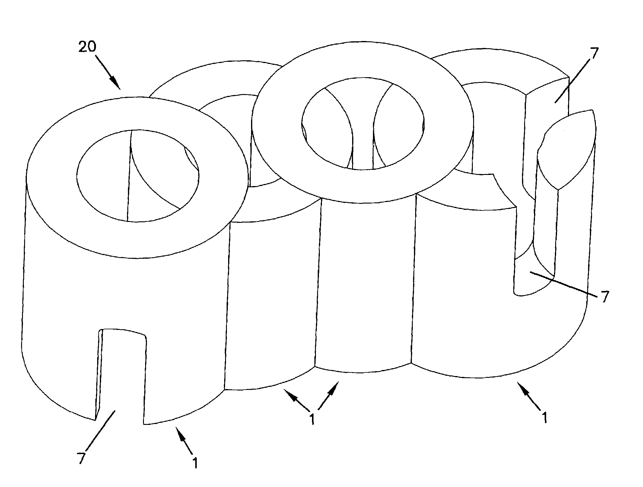
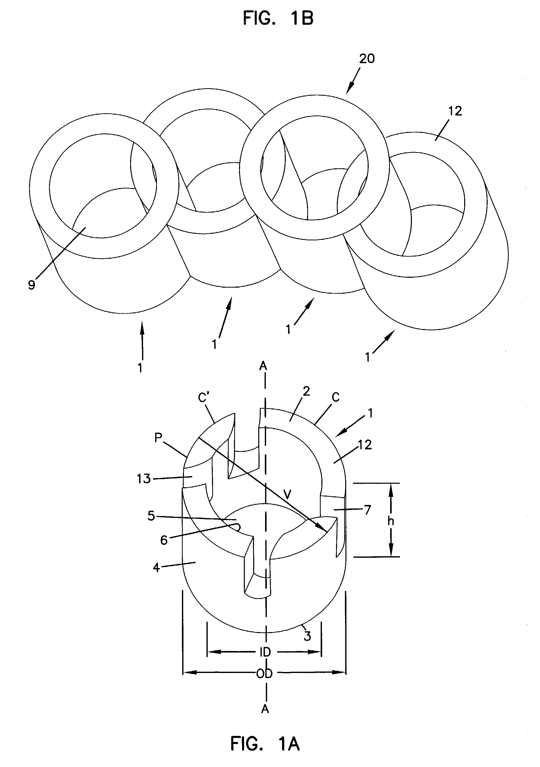
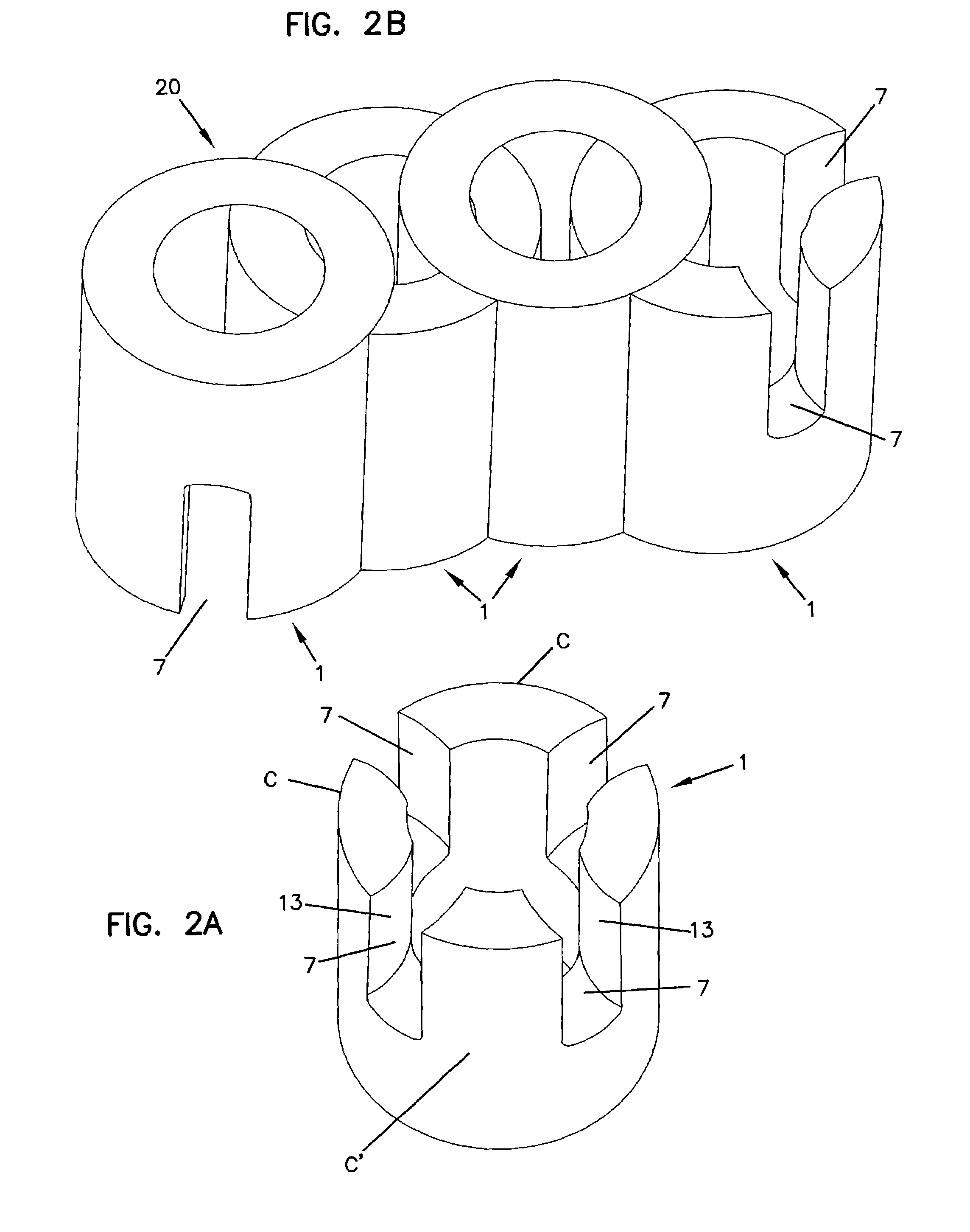
[0040]The invention provides a modular implant for fusing one or more bones. In one embodiment, the modular implant can be used to restore intravertebral disc height and stabilize the vertebral column, while allowing intervertebral (interbody) fusion to occur at the implanted spinal level. Although the disclosure focuses on stabilizing and / or fusing adjacent vertebrae, the invention is not so limited. For example, the invention can be used to fuse other bones, including but not limited to, fractures of or separations in a femur, tibia, humerus, or other long bone. Moreover, the implants are suitable for use with or without additional supporting devices, such as rods, screws, hooks, plates and the like.

[0041]The modular implant is formed from two or more structural elements that can be assembled, pre-implantation, in a variety of shapes and sizes to accommodate varying patient anatomies and surgical procedures. Alternatively, in some embodiments, the structural element ma...


PUM


Abstract

An implant is disclosed for use in stabilization of one or more bones, for example, adjacent vertebrae. The implant includes two or more coupled structural elements. Each structural element includes a first end spaced apart by a side surface from a second end. The side surfaces of each structural element include at least one recess and the structural elements are coupled by matingly engaging one or more recesses.

Description

[0001]This application claims the benefit of priority of U.S. Provisional Patent Application Ser. No. 60 / 368,950, filed Mar. 29, 2002, entitled “Methods and Apparatus for Low Overhead Enhancement of Web Page and Markup Language Presentations,” and which is also claims the benefit of Provisional application No. 60 / 325,585, filed Sep. 27, 2001, the teachings of which are incorporated herein by reference.BACKGROUND[0002]1. Field of the Invention[0003]This invention pertains to a surgical implant for fusing one or more bones. More particularly, the invention relates to a modular implant for use in fusing and / or stabilizing adjacent vertebrae.[0004]2. Description of the Prior Art[0005]Chronic low back pain is one of the most common and perplexing problems facing the field of orthopedic surgery. In addition to patient discomfort, chronic low back pain has severe adverse societal impacts including lost income, possible chronic dependence on drugs or alcohol and public relief programs.[0006...

Claims


Application Information

Patent Timeline
IPC IPC(8): A61F2/44A61B17/56A61F2/00A61F2/28A61F2/30A61F2/46
CPCA61F2/4455A61F2/4611A61F2/28A61F2310/00359A61F2/4465A61F2002/2817A61F2002/2835A61F2002/30075A61F2002/30126A61F2002/30235A61F2002/30271A61F2002/30329A61F2002/30448A61F2002/30449A61F2002/30604A61F2002/30616A61F2002/30677A61F2002/3083A61F2002/30836A61F2002/30841A61F2002/30904A61F2002/4475A61F2002/448A61F2002/4622A61F2002/4628A61F2210/0061A61F2220/0025A61F2220/005A61F2230/0008A61F2230/0069A61F2230/0082A61F2310/00017A61F2310/00023A61F2310/00179A61F2/442A61F2002/30261A61F2002/30593
Inventor HOUFBURG, RODNEY L.
Owner ZIMMER BIOMET SPINE INC
Why Eureka
Try Eureka