Miter saw for displaying angle of cutter blade cutting workpiece

a technology of cutting workpieces and miters, which is applied in the field of miter saws, can solve the problems of affecting work efficiency, affecting work efficiency, and affecting work efficiency, and reducing the number of angle values that can be inscribed on the graduated scales

Active Publication Date: 2006-05-02
KOKI HLDG CO LTD
View PDF9 Cites 27 Cited by
  • Summary
  • Abstract
  • Description
  • Claims
  • Application Information

AI Technical Summary

Benefits of technology

[0019]In view of the foregoing, it is an object of the present invention to provide a miter saw that can provide suitable angle information to a user.
[0020]It is another object of the present invention to provide a miter saw capable of reducing errors in detecting angles during angle adjustments.

Problems solved by technology

However, it is not easy to learn the angles of inclination and rotation instantaneously.
Further, due to space restrictions, there is a restriction on the number of angle values that can be inscribed on the graduated scales.
Hence, the user cannot easily learn the current angles of inclination and rotation instantaneously for angular values other than those inscribed on the graduated scales, leading to a potential drop in work efficiency.
Further, even when a display is provided for displaying the detected angles, the display may not always be used due to malfunctions, various working conditions, or the user's preference.
Therefore, the angle displayed on the display often deviates from the angle determined by a mechanical engagement at a predetermined position or an angle indicated by the graduated scale due to errors in detection or imprecision in the dimensions of the miter saw.
When this happens, the user is provided with multiple values for the angle, inviting confusion that may lead to a decline in working efficiency.
Further, even when the supporting unit is mechanically engaged with the base or turntable at a predetermined position, vibrations or other external forces may cause the angle displayed on the display to change undesirably.
If the angles of inclination and rotation are detected over a broad range, errors in the detected angle may be large, since the angles are always detected bated on a preset reference position.
Hence, it is difficult to display accurate angles of inclination and rotation.

Method used


Image

  • Miter saw for displaying angle of cutter blade cutting workpiece
  • Miter saw for displaying angle of cutter blade cutting workpiece
  • Miter saw for displaying angle of cutter blade cutting workpiece

Examples


Embodiment Construction

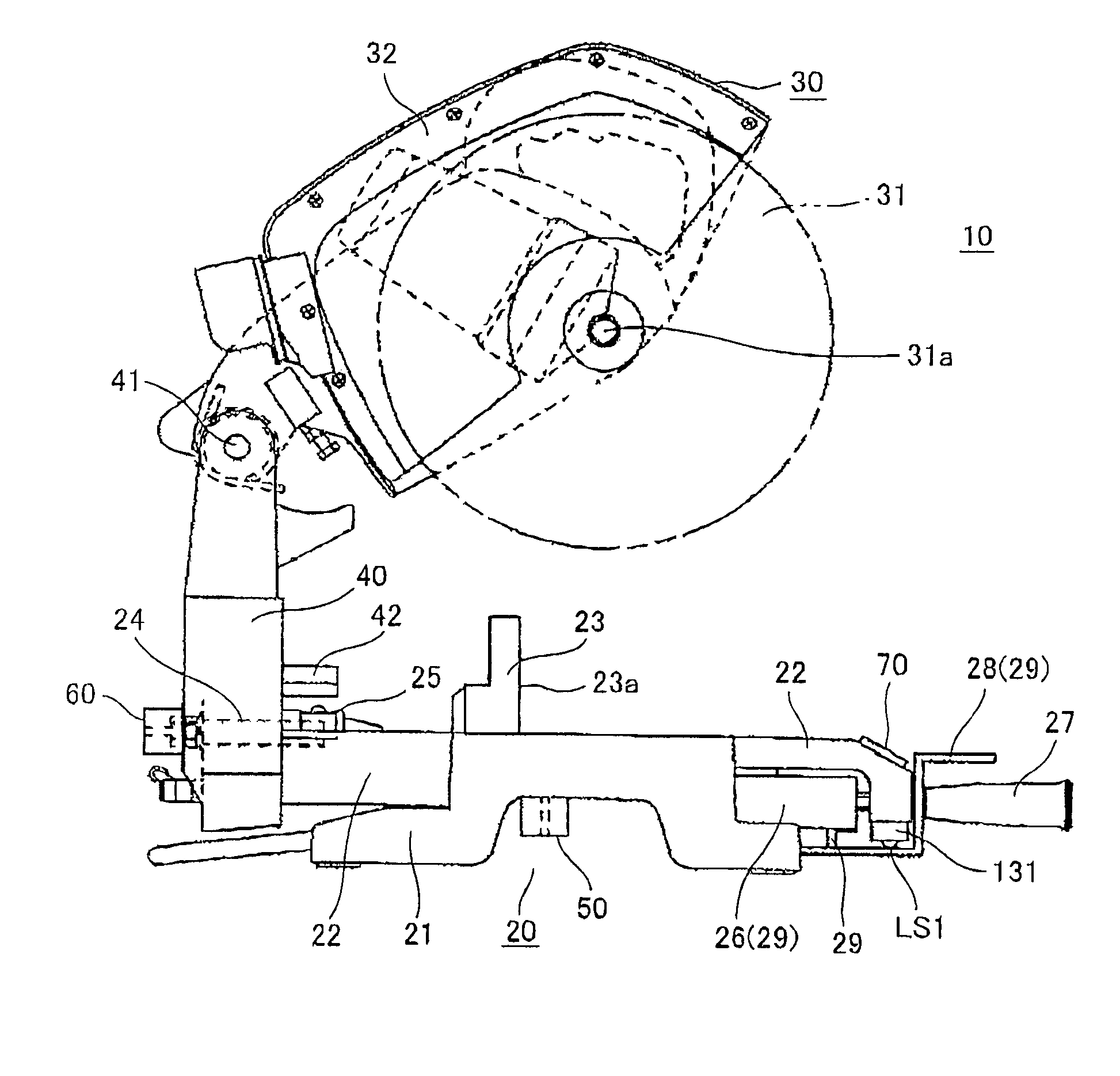
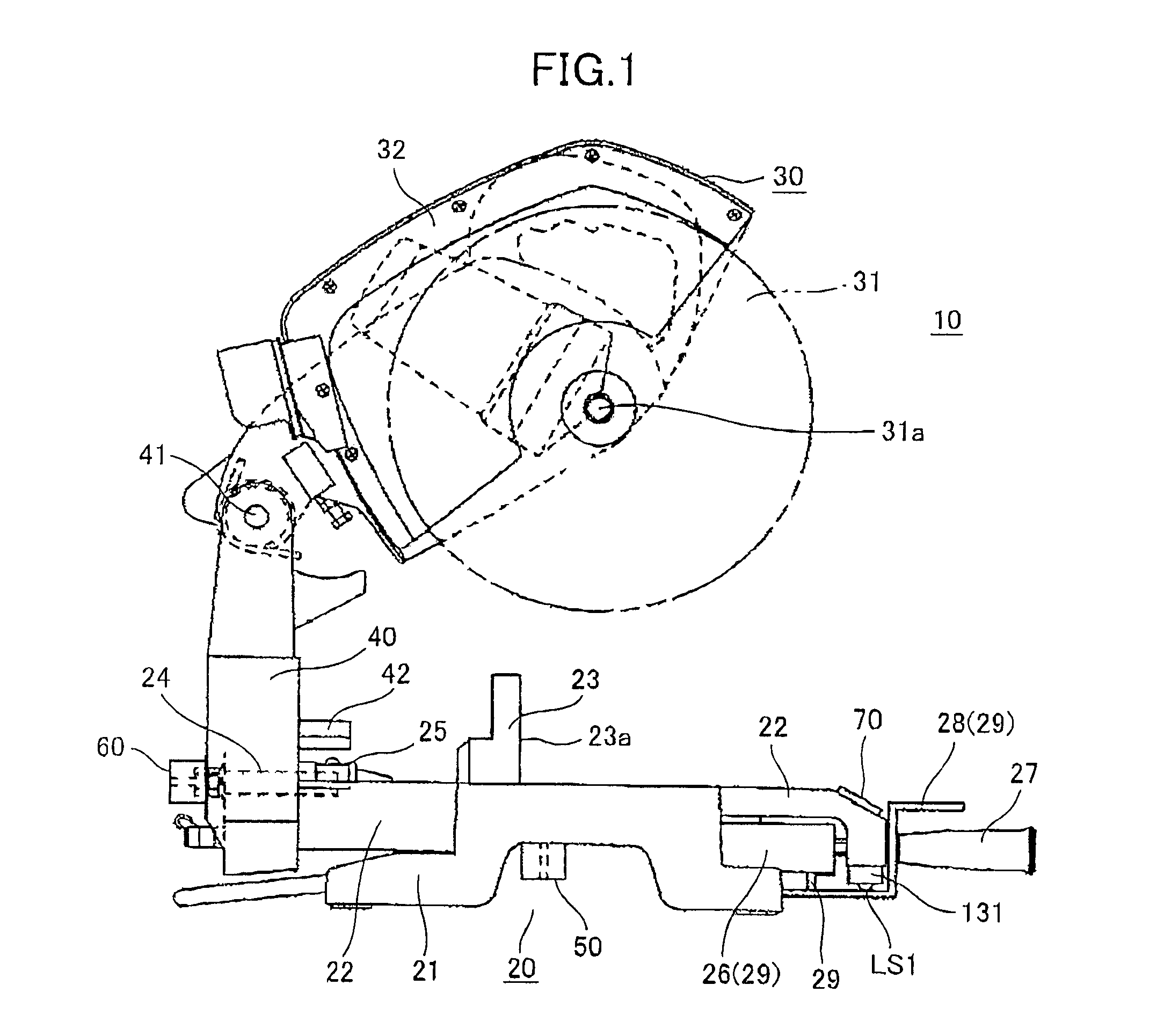
[0038]Next, a miter saw according to a preferred embodiment of the present invention will be described while referring to the accompanying drawings. FIG. 1 shows a miter saw 10 according to the preferred embodiment of the present invention.

[0039]As shown in FIG. 1, the miter saw 10 includes a base unit 20 that is disposed on a flat surface for supporting a workpiece made of wood on the top surface thereof; a cutting unit 30 for cutting the workpiece; and a supporting unit 40 for supporting the cutting unit 30 in a manner that the cutting unit 30 can be moved from an upper position to a lower position to cut down the workpiece. The supporting unit 40 can also be tilted with respect to the top surface of the base unit 20.

[0040]The base unit 20 includes a base 21 placed directly on the flat surface, a turntable 22 that can rotate angularly with respect to the base 21, and a fence 23 having a contact surface 23a that contacts a side surface of a workpiece on the top surface of the base ...


PUM

PropertyMeasurementUnit
inclination angleaaaaaaaaaa
rotation angleaaaaaaaaaa

Abstract

A miter saw for displaying angle of a cutter blade cutting the workpiece. The miter saw has a base mounting a workpiece thereon, a movable member movably supported to the base, and a cutting unit connected to the movable member for supporting the cutter blade. A positioning portion is associated with the movable member and provides a predetermined nominal position of the movable member with respect to the base. The predetermined nominal position includes a reference position and other positions labeled angle. A detector detects the position of the movable member with respect to the base. A processor sets an angle between the reference position and the predetermined nominal position as a displayed moving amount when the movable member is positioned at the predetermined nominal position. Otherwise, the processor computes the moving amount based on the output signal from the detector.

Description

CROSS-REFERENCE TO RELATED APPLICATIONS[0001]This application is based upon and claims the benefit of priorities from Japanese Patent Application No. 2003-350157 filed on Oct. 8, 2003 and Japanese Patent Application No, 2004-217997 filed on Jul. 26, 2004, the entire disclosures of which are hereby incorporated by references in its entirety.BACKGROUND OF THE INVENTION[0002]1. Field of the Invention[0003]The present invention relates to a miter saw capable of adjusting the angle of a circular saw blade in relation to its base and the angle of the circular saw blade in relation to a contact surface of a fence fixed to the base.[0004]2. Description of the Related Art[0005]Conventional miter saws include a base for supporting a workpiece, a cutter blade portion for rotatably supporting a circular saw blade, and a supporting unit for pivotably supporting the circular saw blade about a pivoting shaft that is substantially parallel to the axis of the circular saw blade. The supporting unit ...

Claims


Application Information

Patent Timeline
Patent Type & Authority Patents(United States)
IPC IPC(8): G01C1/00G01B3/56G01B5/24B23D45/04B23D59/00
CPCB23D45/044B23D59/001B23D45/046Y10T83/863Y10T83/8773Y10T83/856
Inventor TAKANO, NOBUHIROOKA, EISAKUOZAWA, HIROMIKAWANO, YOSHIKAZUISHIMARU, KENROUKAWAHARA, TOMOYUKISAITOU, HIROYUKI
Owner KOKI HLDG CO LTD
Why Eureka
Try Eureka