
Motorized scooter

a motorized scooter and scooter technology, applied in the direction of folding cycles, cycles, transmissions with friction rollers, etc., can solve the problems of affecting the balance of the scooter, causing tiring for the operator, and adding a lot of weigh

Inactive Publication Date: 2006-05-09
GO SPORTING GOODS
View PDF25 Cites 52 Cited by
  • Summary
  • Abstract
  • Description
  • Claims
  • Application Information

AI Technical Summary

Problems solved by technology

This can be tiring for the operator over long distances.
However, the addition of the battery and motor assembly adds tremendous weight and upsets the balance of the scooter as the weight is distributed towards the front portion of the scooter.
Thus, the larger the battery, the more upset the balance of the scooter becomes.
In another approach, the motor and battery assembly is attached to drive the rear wheel, but this approach also encounters similar problems with improper weight distribution.
Moreover the mounting of the motor as an add-on does not provide the most efficient or consistent contact with the drive wheel.
For example, when the scooter goes over a bump or over rough terrain, the motor might become temporarily disconnected from the drive wheel as the motor and battery assembly is not always attached securely or properly to the scooter, and hence the wheel.
Although the integration of the battery and motor to the scooter as “original” equipment solves some problems, it causes others.
For example, the addition of the transmission increase the base cost of the scooter, and is another point of failure.
In addition, once the battery runs out, the motor has to be disengaged from the drive wheel.
Further, as the motor is typically mounted such that the axis of the motor is parallel to the axis of the wheel, the body of the motor often protrudes out of either the left or right side of the scooter, affecting the balance of the scooter, interfering with the rider's kick stroke, and increasing the risk of damage to the motor due to the exposure (or impact) of the motor to outside elements.

Method used


Image

  • Motorized scooter
  • Motorized scooter
  • Motorized scooter

Examples


Embodiment Construction

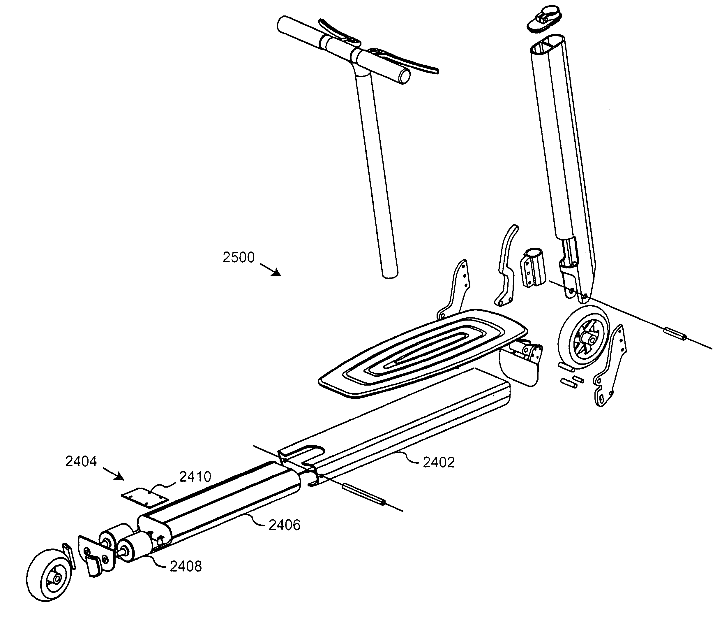
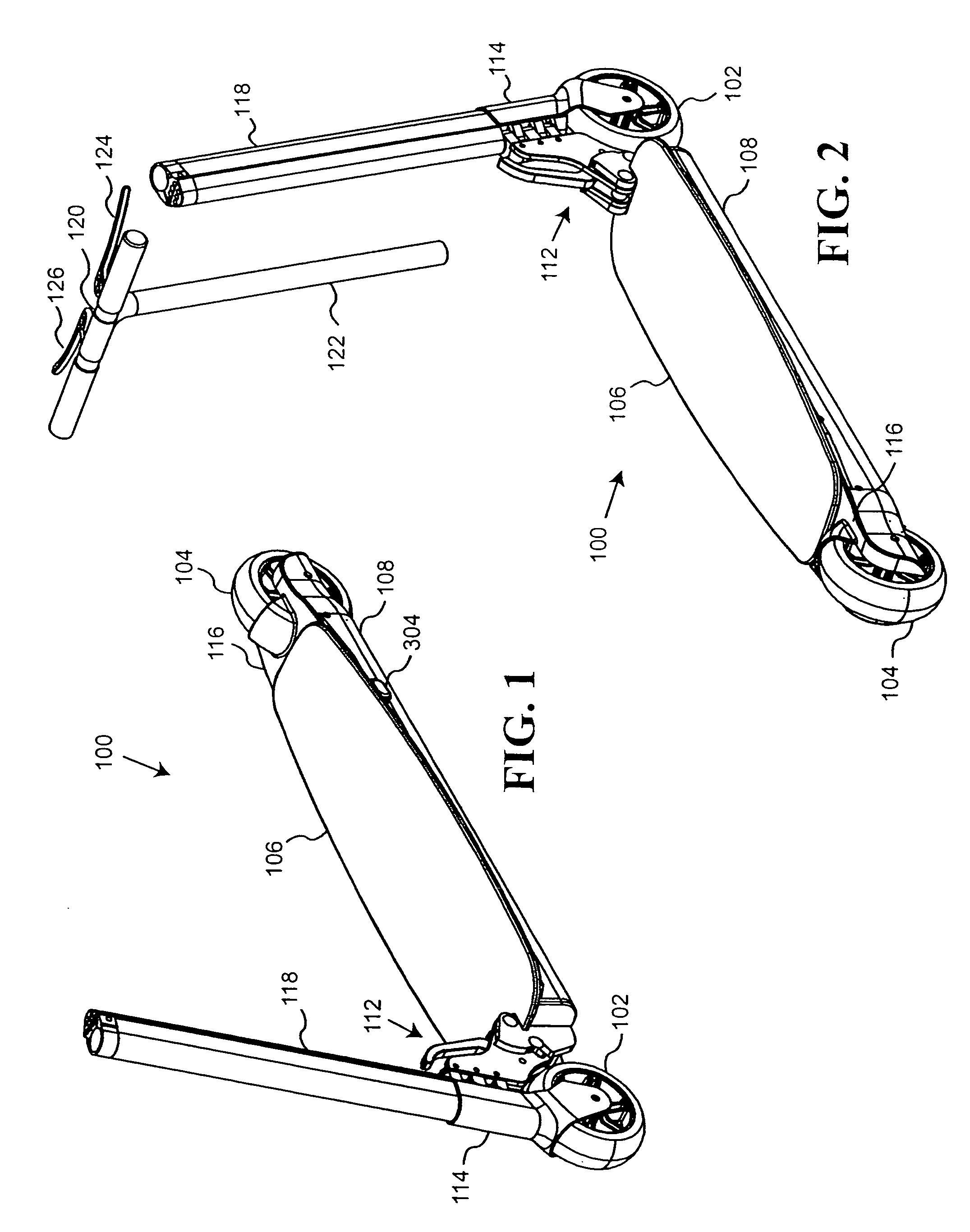
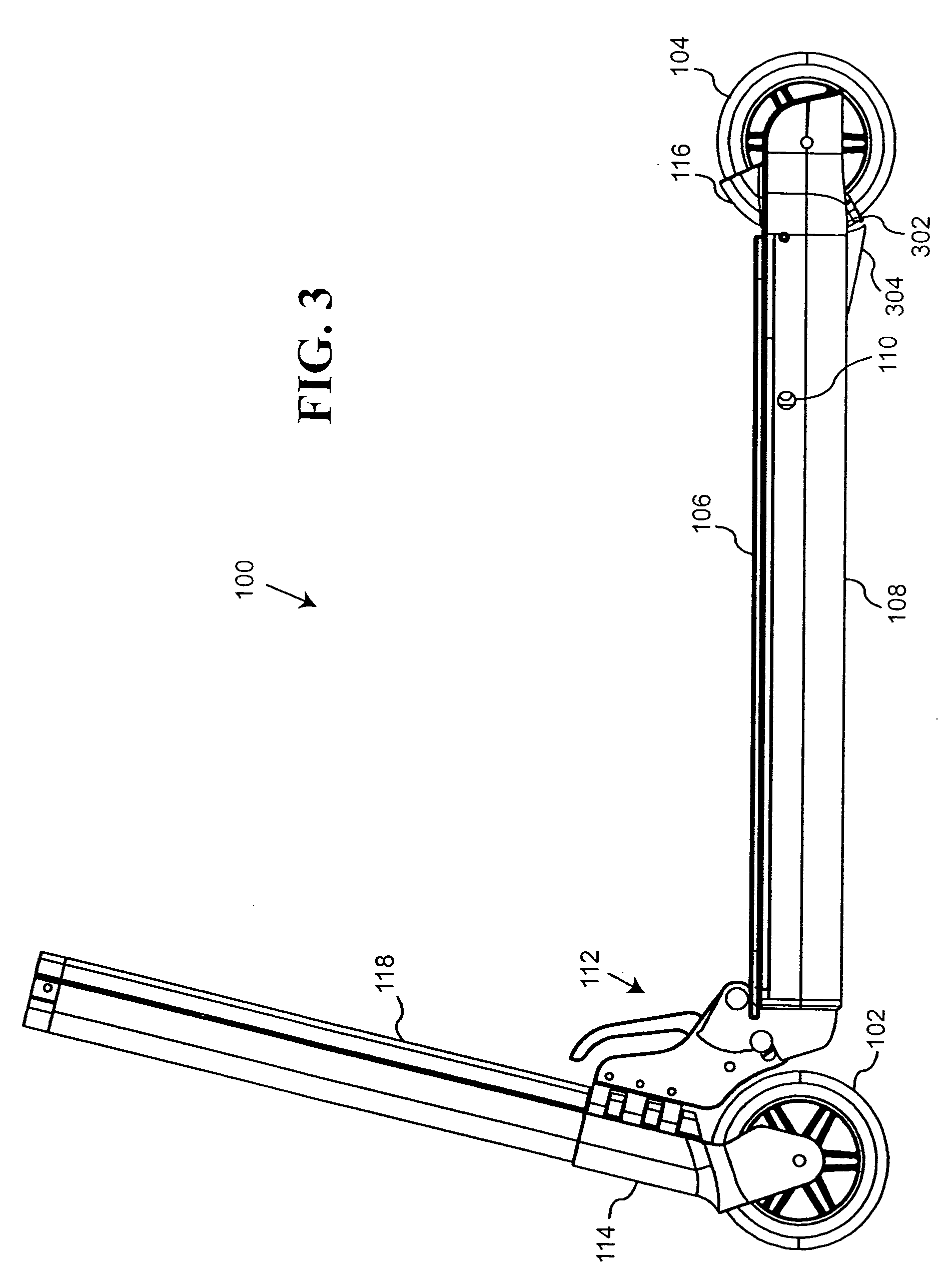
[0007]The present invention provides a motorized scooter with a battery, motor and transmission assembly that is integrated into a fuselage of the motorized scooter; and a folding hinge and steering mechanism.

[0008]In one preferred embodiment of the present invention, the scooter includes a fuselage with a front portion and a rear portion that has a rear wheel rotatably mounted at the rear portion. The scooter also includes a standing platform supported by the fuselage for supporting a rider and a transmission system mounted under the standing platform in the rear portion of the fuselage. The transmission system has a motor with a wheel engagement element being operatively coupled with the rear wheel to allow the wheel engagement element to rotate the rear wheel when the wheel engagement element is engaged with the rear wheel.

[0009]In one embodiment of the present invention, the transmission system includes a dual-motor direct drive system for driving a wheel, each motor having a mo...


PUM


Abstract

A scooter having a fuselage with a front portion and a rear portion that includes a rear wheel rotatably mounted at the rear portion. The scooter also includes a standing platform supported by the fuselage for supporting a rider and a transmission system mounted under the standing platform in the rear portion of the fuselage. The transmission system having a motor with a wheel engagement element being operatively coupled with the rear wheel to allow the wheel engagement element to rotate the rear wheel when the wheel engagement element is engaged with the rear wheel. Another embodiment of the transmission system includes a motor, a first drive cone coupled the motor; and, a drive cone engagement mechanism configured to allow the first drive cone to be operatively coupled with a wheel to rotate the wheel.

Description

FIELD OF THE INVENTION[0001]The present invention relates generally to motorized scooters, and more particularly, to an electric scooter with low profile propulsion system.BACKGROUND OF THE INVENTION[0002]Many types of scooters currently exist on the market. One type of scooter is “kick” or “push” scooters that require riders to manually propel the scooter. Although economical to operate as it requires no fuel, kick scooters relies on the operator to propel it. This can be tiring for the operator over long distances. An optional add-on to the kick scooter is a motor and battery system. Typically, the motor and battery is integrated into a single housing, with the drive shaft of the motor protruding from the housing. The housing is rigged to the steering column of the scooter such that the drive shaft of the motor contacts the front wheel of the scooter to drive the wheel (“the drive wheel”).[0003]As the run time of the motor is proportional to the capacity of a battery, a fairly lar...

Claims


Application Information

Patent Timeline
IPC IPC(8): B62M1/20
CPCB62K3/002B62K2202/00B62K2204/00B62K15/006
Inventor ROTH, DAVIDDIENER, LAWRENCEGOETZ, DAVID R.
Owner GO SPORTING GOODS
Learn More