Easy entry seat with seat back mounted floor latch

Inactive Publication Date: 2006-05-09
INTIER AUTOMOTIVE INC
View PDF19 Cites 56 Cited by
  • Summary
  • Abstract
  • Description
  • Claims
  • Application Information

AI Technical Summary

Benefits of technology

[0008]According to one aspect of the invention there is provided a seat assembly for use in an automotive vehicle. The seat assembly comprises a seat cushion and a seat back pivotally assembled to the seat cushion for movement between a plurality of reclined seating positions including a fully reclined seating position relative to the seat cushion. A recliner mechanism is operatively coupled between the seat cushion and the seat back for selectively locking the seat back between any one of the plurality of reclined seating positions. A front link extends between one end pivotally coupled to the seat cushion and an opposite end pivotally coupled to the floor of the vehicle for supporting the seat cushion in a seating position above the floor of the vehicle and for guiding the seat cushion between the seat position and a flat position against the floor of the vehicle. The seat assembly includes a rear floor latch for releasably locking the seat cushion in the seating position to a striker bar fixedly secured to the floor of the vehicle and unlocking the seat cushion and the seat back for movement between the seating position and an upright position with both of the seat cushion and seat back extending generally upright from the floor of the vehicle. A rear support link is operatively coupled between the seat assembly and the floor of the vehicle for supporting and securing the seat cushion and the seat back in the upright position and for guiding the seat assembly between the seating and upright positions.

Problems solved by technology

However, such riser assemblies require space to accommodate the motion of the seat assembly between the seating and forwardly stowed positions while the seat back is in the folded position against the seat cushion.

Method used


Image

  • Easy entry seat with seat back mounted floor latch
  • Easy entry seat with seat back mounted floor latch
  • Easy entry seat with seat back mounted floor latch

Examples


Embodiment Construction

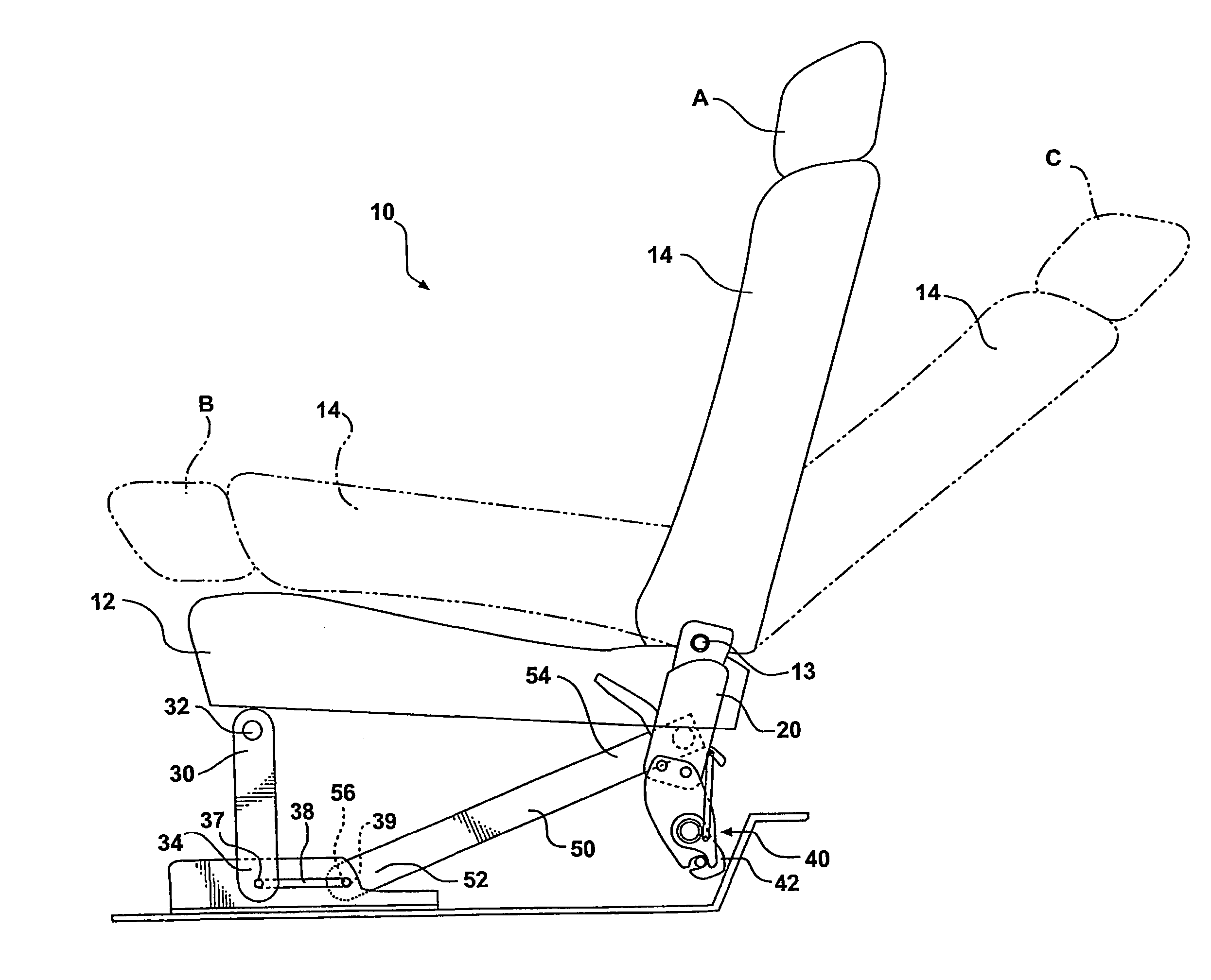
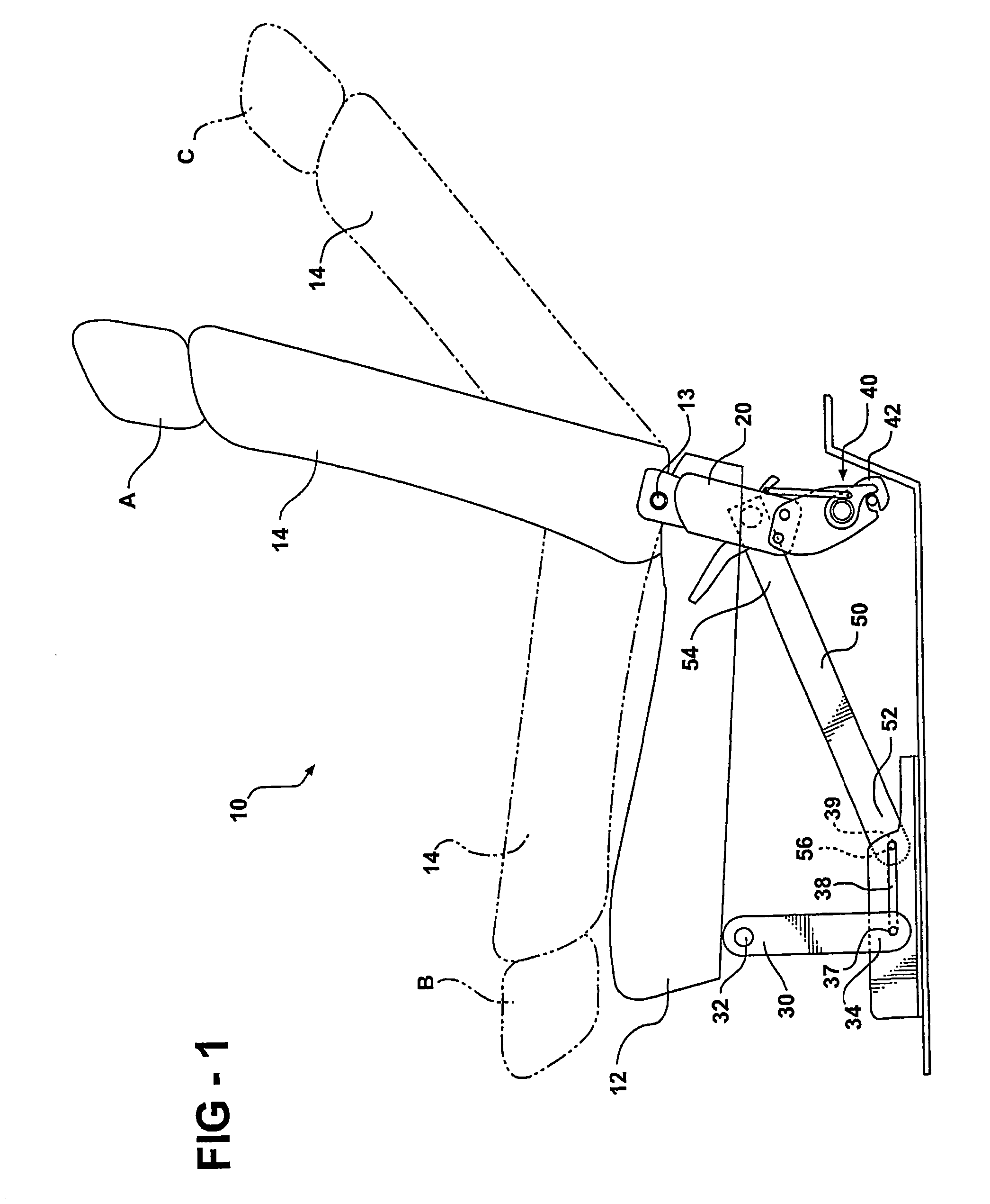
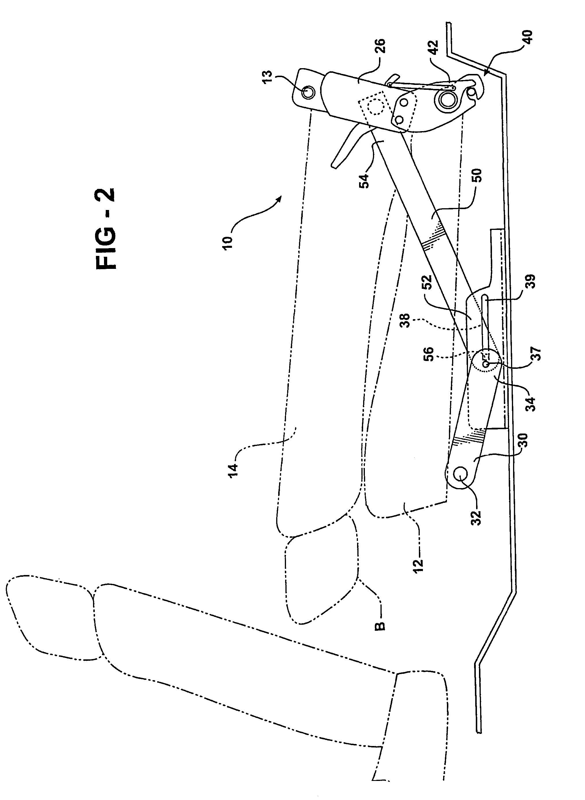
[0014]Referring to FIGS. 1–3, a seat assembly 10 is shown for supporting an occupant above a floor 16 of an automotive vehicle. The seat assembly 10 includes a seat cushion 12 and a seat back 14 pivotally coupled to the seat cushion 12 by a pivot pin 13 for pivotal movement of the seat back 14 about the pivot pin 13 relative to the seat cushion. As shown in FIG. 1, a recliner assembly 20 is operatively coupled between the seat cushionl2 and the seat back 14 for allowing selective locking and pivotal adjustment of the seat back 14 relative to the seat cushion 12 between a generally upright seating position A, a forwardly folded position B generally overlying the seat cushion 12, and a fully reclined seating position C.

[0015]Referring to FIG. 4, the recliner mechanism 20 includes a sector of teeth 22 formed in a bracket 24 fixedly secured to the seat back 14. The sector of teeth 22 are generally centered about the pivot pin 13. A pawl 24 having a rack of teeth lockably engagable with ...


PUM


Abstract

A seat assembly for use in an automotive vehicle comprises a seat cushion and a seat hack pivotally connected to the seat cushion by a recliner mechanism for providing pivotal movement of the seat back between a plurality of reclined seating positions and a forwardly folded position against the seat cushion. A front link supports the scat cushion above the floor of the vehicle in the seating position and lowers the seat cushion to a flat position with the seat back in the folded position. A rear floor latch releasably secures the seat cushion to the floor of the vehicle in the seating position and unlocks the seat cushion and the seat back for pivotal movement about the front link from the seating position to an upright tilted position with each of the seat cushion and the seat back extending generally upright from the floor of the vehicle. A rear link is operatively coupled between the seat back and the floor of the vehicle for supporting and securing the seat cushion and the scat back in the tilted position.

Description

[0001]This application claims the benefit of Provisional Application Ser. No. 60 / 294,131, filed May 29, 2001.BACKGROUND OF THE INVENTION[0002]1. Field of Invention[0003]The subject invention relates to a seat assembly for an automotive vehicle, and more particularly, to a fold and tilt mechanism operatively coupled between a seat back and a seat cushion of the seat assembly for moving the seat assembly between a seating position, a folded position with the seat back pivoted against the seat cushion and an upright tilted position with the seat cushion pivoted forwardly and generally upright and the seat back pivoted about the seat cushion to an upright position.[0004]2. Description of the Related Art[0005]Automotive vehicles include seat assemblies for supporting occupants within the vehicle cabin. Seat assemblies include a generally horizontal seat cushion and a generally upright seat back for supporting the back of an occupant seated upon the seat cushion. Typically, a recliner ass...

Claims


Application Information

Patent Timeline
Patent Type & Authority Patents(United States)
IPC IPC(8): B60N2/10B60N2/20B60N2/235B60N2/36B60N2/30
CPCB60N2/206B60N2/309B60N2/3065B60N2/3011
Inventor TAME, OMAR D.KAYTSER, ALEXANDER VICTOR
Owner INTIER AUTOMOTIVE INC
Why Eureka
Try Eureka