Automated meter reader device having optical sensor with automatic gain control

a technology of automatic gain control and meter reading information, which is applied in the direction of optical radiation measurement, instruments, sustainable buildings, etc., can solve the problems of wasting a lot of time and money in obtaining meter reading information

Inactive Publication Date: 2006-05-09
PINE TREE HLDG
View PDF10 Cites 74 Cited by
  • Summary
  • Abstract
  • Description
  • Claims
  • Application Information

AI Technical Summary

Problems solved by technology

Utilities correctly perceive these meters as their “cash registers” and they spend a lot of time and money obtaining meter reading information.
Usually these “drive by” or “walk by” AMR products operate under Part 15 of the FCC Rules, primarily because of the scarcity of, or the expense of obtaining, licenses to the RF spectrum.

Method used


Image

  • Automated meter reader device having optical sensor with automatic gain control
  • Automated meter reader device having optical sensor with automatic gain control
  • Automated meter reader device having optical sensor with automatic gain control

Examples


Embodiment Construction

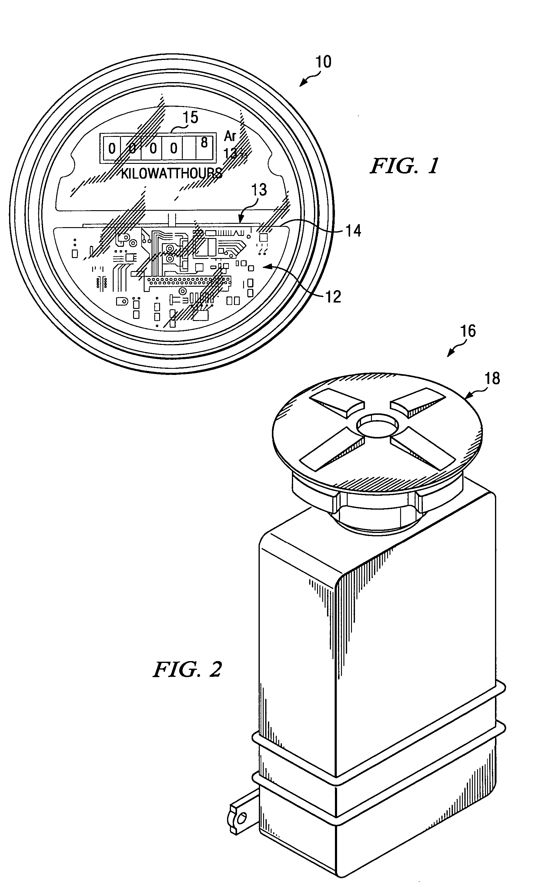
[0034]Referring now to FIG. 1, there is illustrated a household electric meter unit generally shown at 10 having adapted therewith an electric meter reading unit 12 according to a first preferred embodiment of the present invention coupled to sense a black spot 13 on the rotating meter disk generally shown at 14. Electric meter unit 12 has an optical sensor for detecting the passing of the back spot 13 therepast to ascertain the consumed amount of electricity correlated to the read out of the visual display 15 of meter unit 10.

[0035]FIG. 2 is the perspective view of a water meter unit according to a second preferred embodiment of the present invention generally being shown at 16. The circular structure 18 on the top of device 16 is adapted to fasten the unit 16 onto a water meter pit lid (not shown) with an antenna node (not shown) sticking up through a hold drilled through the pit lid.

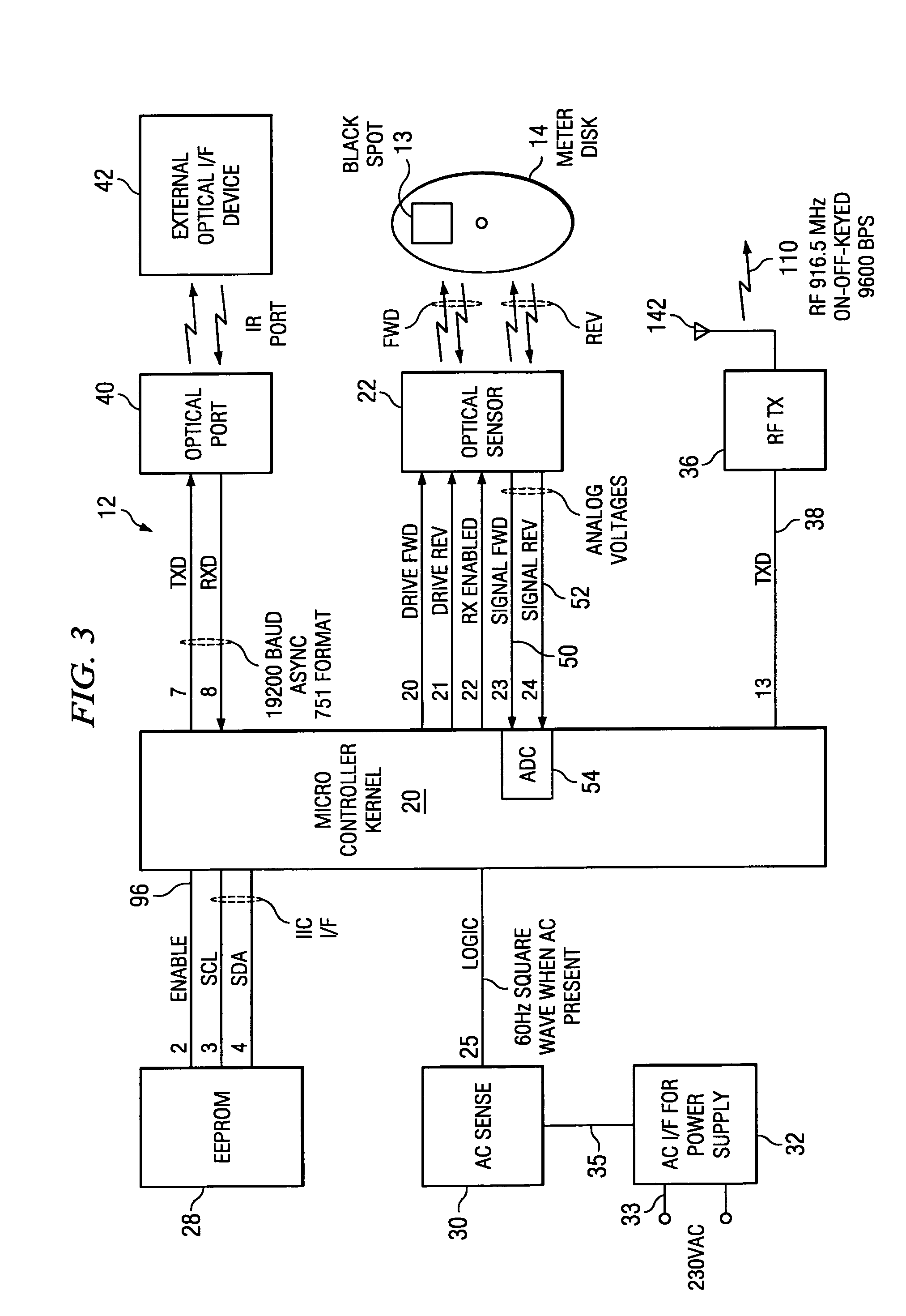
[0036]Referring now to FIG. 3, there is illustrated an electrical block diagram of the electric me...


PUM


Abstract

The present invention achieves technical advantages as an AMR device and method of use having an optical transceiver adapted to read analog meter faces. The transceiver advantageously includes an optical receiver having an amplifier receiving signals from photodiodes and further including an automatic gain control. A gain of the optical receiver amplifier is programmable to compensate for parameters affecting the photodiodes in the optical receiver.

Description

CROSS REFERENCE TO RELATED APPLICATIONS[0001]This application is a continuation-in-part (CIP) of co-pending U.S. patent application Ser. No. 09 / 896,502 entitled “Optical Sensor for Utility Meter” filed Jun. 29, 2001 now U.S. Pat. No. 6,798,352, which is a continuation of U.S. patent application Ser. No. 09 / 419,743 filed Oct. 16, 1999, now issued as U.S. Pat. No. 6,710,721.FIELD OF THE INVENTION[0002]The present invention is generally related to utility meter reading devices, and more particularly to automated devices utilized to remotely and efficiently obtain meter readings of utility meters providing electric, gas and water service.BACKGROUND OF THE INVENTION[0003]Organizations which provide electric, gas and water service to users are commonly referred to as “utilities”. Utilities determine charges and hence billings to their customers by applying rates to quantities of the service that the customer uses during a predetermined time period, generally a month. This monthly usage is...

Claims


Application Information

Patent Timeline
Patent Type & Authority Patents(United States)
IPC IPC(8): G08B23/00G01D4/00G08C19/12
CPCG01D4/006G01D4/008G08C19/12Y04S20/50Y02B90/247Y04S20/325Y02B90/243Y02B90/20Y04S20/30
Inventor PATTERSON, TIMHOLOWICK, ERWINDERRY, KENNETH J.PINKHAM, JASON R.
Owner PINE TREE HLDG
Why Eureka
Try Eureka