
Missile-borne explosive activated grenade release device

a technology of explosive activation and release device, which is applied in the direction of weapons, ammunition projectiles, projectiles, etc., can solve the problems of detonation at the target, and achieve the effect of facilitating the opening of the forward conical portions

Inactive Publication Date: 2006-05-16
GOVERNMENT OF THE UNITED STATES AS REPRESENTED BY THE SEC OF THE US ARMY
View PDF5 Cites 2 Cited by
  • Summary
  • Abstract
  • Description
  • Claims
  • Application Information

AI Technical Summary

Benefits of technology

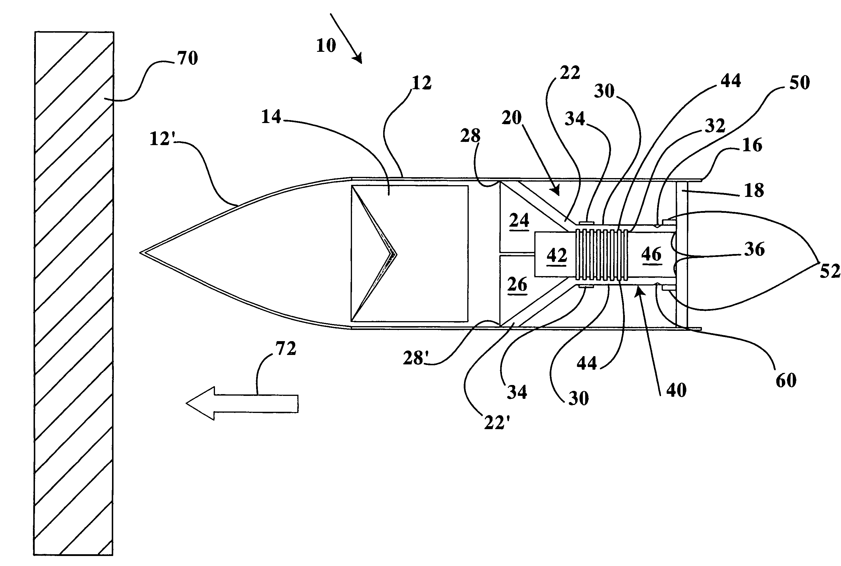
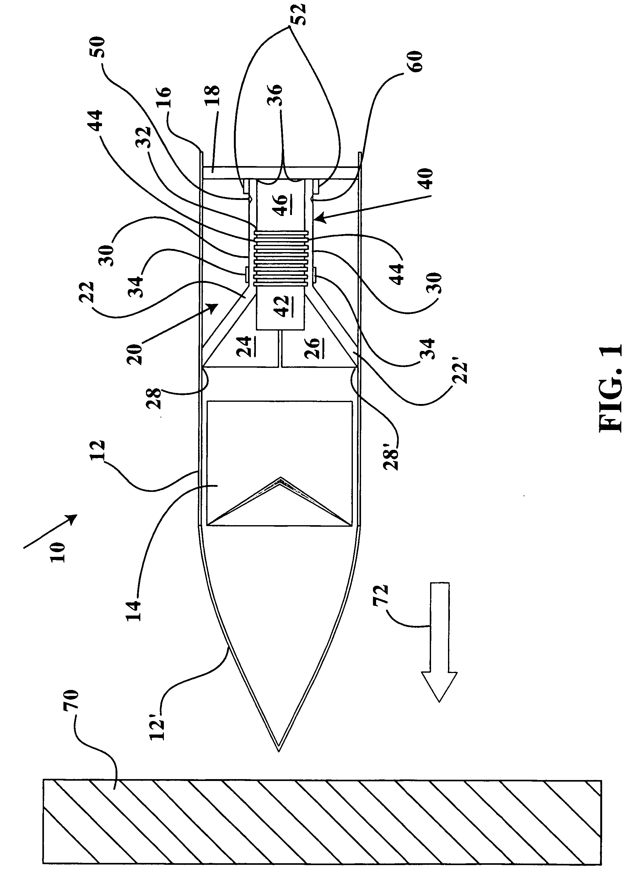
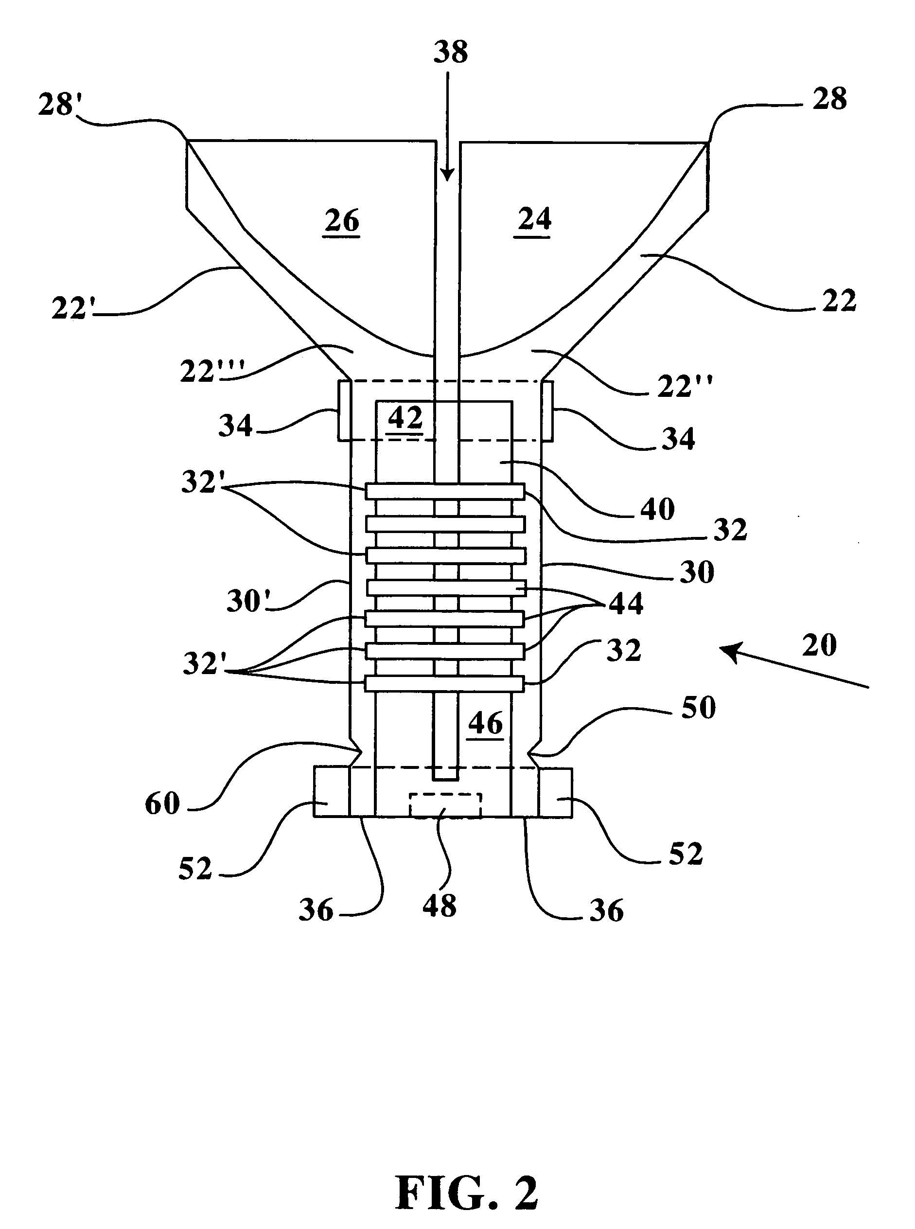
[0013]The forward conical portion of each segmented cylindrical unit is maintained in a conical configuration behind the first explosive charge during flight. Upon detonation of the first explosive charge against a target surface, the forward conical portions are forced outwards and backwards by release of high pressure gasses from the detonated first explosive charge. In order to facilitate the opening of the forward conical portions, a designed weakness within the rear outer surface of each segmented cylindrical unit is provided by at least one circumferential groove therein. The circumferential grooves form a first and second hinged configuration for each rear outer surface of each segmented cylindrical unit. The circumferential grooves are positioned forward of the rear securing ring when the release body is assembled and disposed within the munition shell. Upon detonation of the first explosive charge against a target surface, an opening process similar to the opening of flower petals will occur for the release device in order to provide a forward directed release of the second explosive charge. The detonation of the first explosive charge provides high pressure gases directed forward and rearward. The rearwardly directed gasses impact the forward surfaces of the partial cone portions, resulting in each partial cone portion being forced apart and backwards. During the forced opening of each partial cone portion, an outwards pivoting pressure is applied at each circumferential groove forward of the rear securing ring, thereby allowing each cylindrical unit to pivot apart similar to flower petals opening outwards. Pivoting of each cylindrical unit provides release of the second explosive charge and allows forward movement to impact and explode at the pre-stressed target surface, thereby focusing a second sequence of high pressure gasses against the target surface in order to breach the target surface.

Problems solved by technology

If a prior grenade or missile launcher does not provide adequate time delay or accuracy for delivery between first, second, and additional missiles to the target structure, either due to miscalculations by operator, malfunctions in software controlling the launcher, or movement of the launcher or the target, the additional missiles may not acquire and detonate at the target in close succession to maximize damage to the target structure.

Method used


Image

  • Missile-borne explosive activated grenade release device
  • Missile-borne explosive activated grenade release device
  • Missile-borne explosive activated grenade release device

Examples


Embodiment Construction

[0022]Referring now to FIGS. 1–7B, a missile-borne release device 10 is disclosed including a forwardly disposed first explosive device 14 and a rearwardly disposed second explosive device 40 axially aligned within a munition shell 12. The release device 10 within the munition shell 12 is delivered to a hardened target surface 70 for sequential detonation of the first explosive device 14 followed by detonation of the second explosive device 40 to generate sequential and forwardly directed high pressure gas and shock waves of sufficient magnitude to breach the hardened target surface 70. The release device 10 is readily utilizable by infantry and is adaptable for release from piloted or remote controlled aircraft, and vehicles transporting and / or supporting infantry during urbane warfare. The release device 10 is further utilizable in the commercial demolition industry for destruction of hardened structures by directed delivery of multiple explosive devices having sufficient destruct...


PUM


Abstract

A delivery and release device for release and detonation of sequential explosive charges is disclosed to penetrate hardened structures. An aerodynamic shell is sized for delivery to a target by hand or mechanical means, including a first explosive charge is in a forward portion and a release device enclosing a second explosive charge is disposed in a shell rear portion. The release device includes a segmented cone positioned behind the first explosive charge, and a segmented cylindrical unit extending rearwards to enclose the second explosive charge within the shell during flight. Upon impact with the target, the first explosive charge detonates and directs high pressure gases against the target and deflection of gases rearwards against the segmented cone. The segmented cone and cylindrical unit are forced to separate and pivot outwards thereby releasing the second explosive charge for delayed delivery and detonation against the target leading to breach and destruction.

Description

STATEMENT REGARDING FEDERALLY SPONSORED RESEARCH OR DEVELOPMENT[0001]The invention described herein may be manufactured, used and licensed by or for the Government for governmental purposes without the payment to the inventors of any royalties thereon.CROSS-REFERENCE TO RELATED APPLICATIONS[0002]Not Applicable.BACKGROUND OF THE INVENTION[0003]1. Field of the Invention[0004]The invention relates to devices for release and directed delivery of explosive devices. More specifically, the present invention relates to a missile-borne grenade delivered by a release unit providing directed explosive force at a target.[0005]2. Description of the Related Art[0006]The use of hand-released grenade, missile and munition packages are well known in warfare (hereinafter referred to as “explosive unit” or “grenade”). Typically the explosive unit and any associated delivery device(s) are used to attack target structures such as buildings, bunkers and other fortifications before entry by infantry. Prio...

Claims


Application Information

Patent Timeline
IPC IPC(8): F42B12/02
CPCF42B12/16F42B14/062F42B12/204
Inventor CORNELIUS, CHARLES STEPHENVESSELS, CHARLES M.
Owner GOVERNMENT OF THE UNITED STATES AS REPRESENTED BY THE SEC OF THE US ARMY
Learn More