
USB flash-memory card with perimeter frame and covers that allow mounting of chips on both sides of a PCB

a flash memory card and perimeter frame technology, applied in the direction of coupling device connection, coupling protective earth/shielding arrangement, instruments, etc., can solve the problems of unreliability, flash memory card is cheap, and the manufacturing cost is increased

Inactive Publication Date: 2006-05-16
SUPER TALENT ELECTRONICS
View PDF11 Cites 48 Cited by
  • Summary
  • Abstract
  • Description
  • Claims
  • Application Information

AI Technical Summary

Problems solved by technology

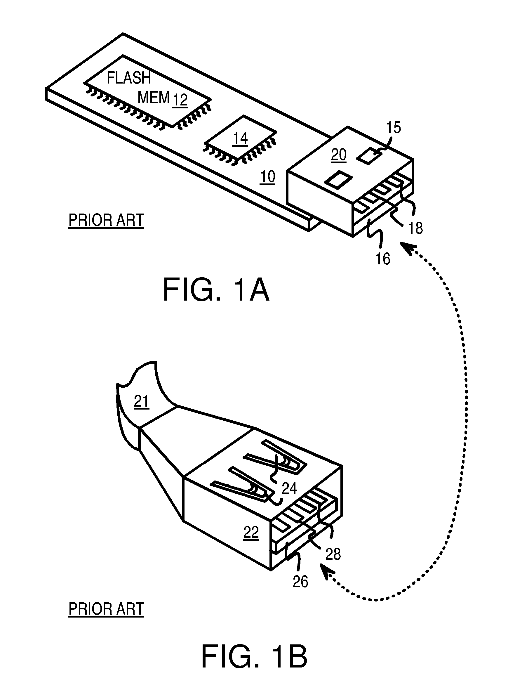
The metal case in particular is cumbersome and increases manufacturing cost.
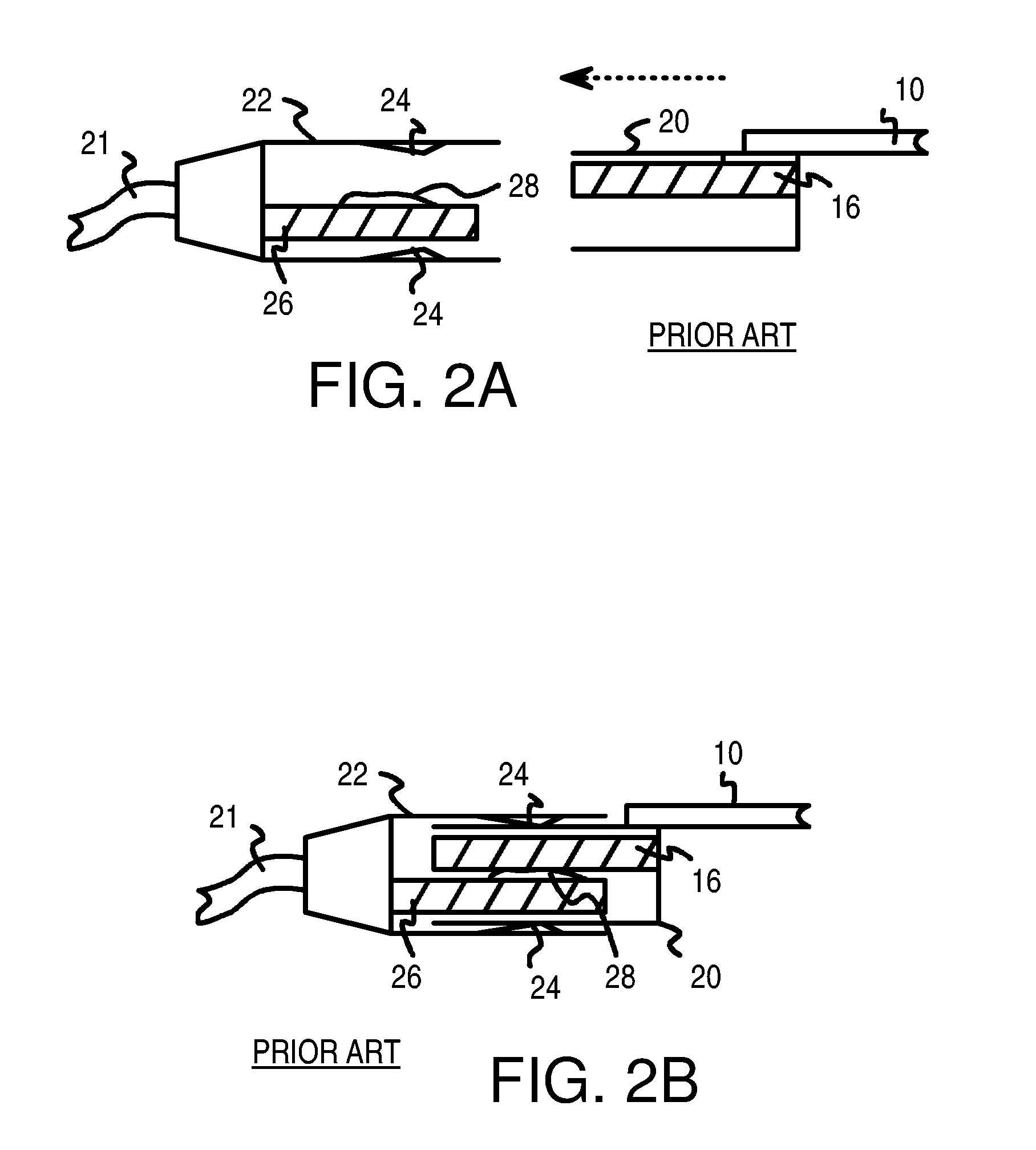
This vertical play gives the user the feeling that the flash memory card is cheap and unreliable, even when sufficient electrical contact is made.

Method used


Image

  • USB flash-memory card with perimeter frame and covers that allow mounting of chips on both sides of a PCB
  • USB flash-memory card with perimeter frame and covers that allow mounting of chips on both sides of a PCB
  • USB flash-memory card with perimeter frame and covers that allow mounting of chips on both sides of a PCB

Examples


Embodiment Construction

[0031]The present invention relates to an improvement in flash-memory devices with slim USB connectors. The following description is presented to enable one of ordinary skill in the art to make and use the invention as provided in the context of a particular application and its requirements. Various modifications to the preferred embodiment will be apparent to those with skill in the art, and the general principles defined herein may be applied to other embodiments. Therefore, the present invention is not intended to be limited to the particular embodiments shown and described, but is to be accorded the widest scope consistent with the principles and novel features herein disclosed.

[0032]The inventors have discovered that a variety of manufacturing methods may be used to make the flash-memory card with supporting dividers between the USB metal pads. In particular, a perimeter frame that surrounds the printed-circuit board (PCB) can increase strength of the device. Such perimeter fra...


PUM


Abstract

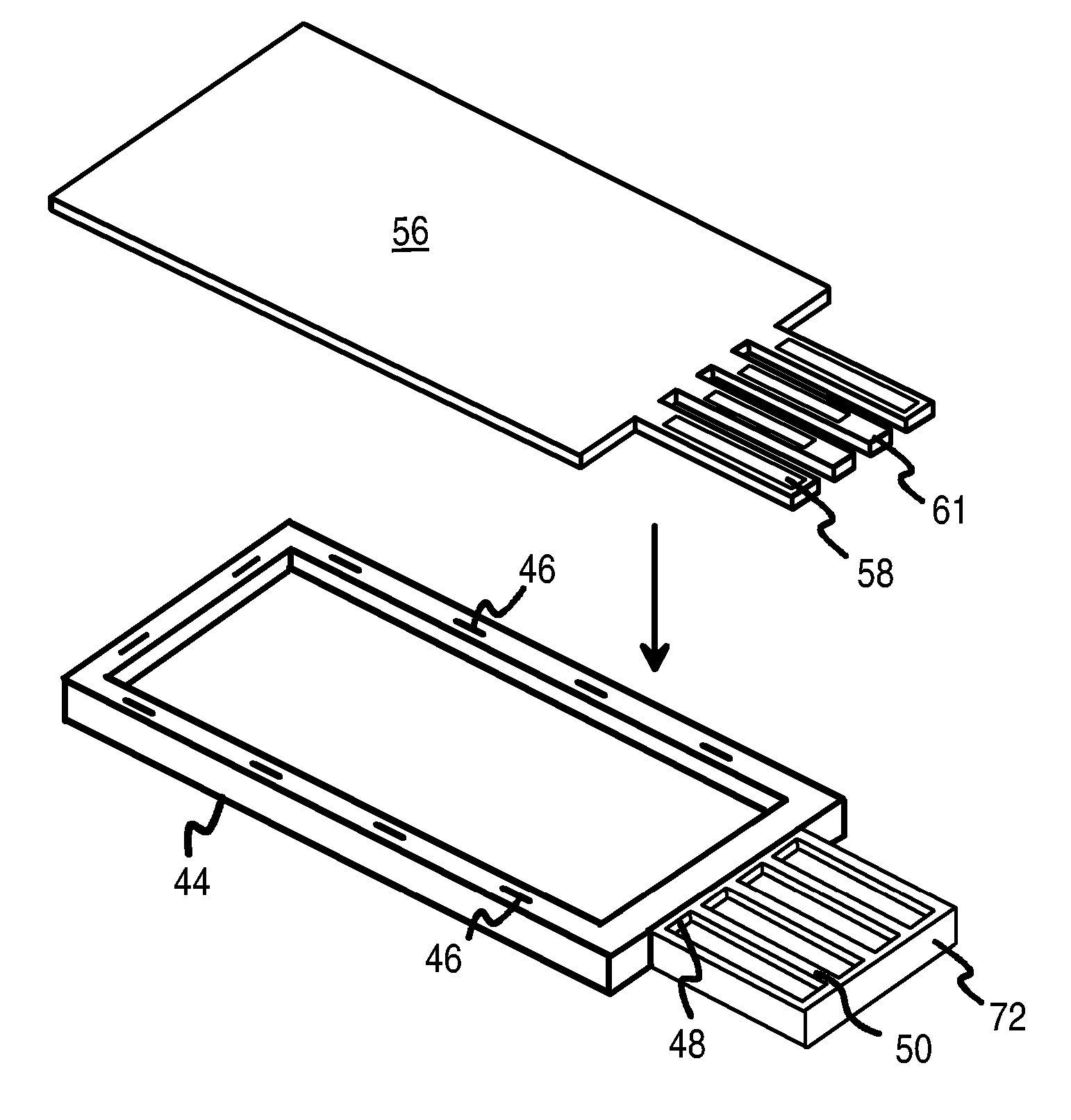
A flash-memory-drive card has a Universal-Serial-Bus (USB) connector. The card has a printed-circuit board (PCB) that fits into a perimeter frame that surrounds the edges of the PCB. Metal or plastic upper and lower covers are snapped onto the frame to encapsulate the PCB. The USB connector can be a Full USB connector plug that extends from the perimeter frame and has a centerline approximately matching the PCB centerline for a balanced design, or can be a slim or reduced-height USB connector plug that has a frame closure bar that fits inside closure fittings on the perimeter frame. The USB connector can also be made from a frame extension that has four frame slots through the frame. The PCB has four PCB fingers that are inserted through the frame slots during assembly so that the PCB fingers fit within depressions in the frame extension to form the USB connector plug.

Description

RELATED APPLICATIONS[0001]This application is a continuation-in-part of the co-pending application for “Slim USB Connector with Spring-Engaging Depressions, Stabilizing Dividers and Wider End Rails for Flash-Memory Drive”, U.S. Ser. No. 10 / 605,146, filed Sep. 19, 2003, now U.S. Pat. No. 6,854,984 and “Manufacturing Methods for Ultra-Slim USB Flash Memory Card with Supporting Dividers or Underside Ribs”, U.S. Ser. No. 10 / 904,207, filed Oct. 28, 2004.FIELD OF THE INVENTION[0002]This invention relates to flash-memory-drive cards, and more particularly to frame-based manufacturing methods for cards with reduced-height Universal-Serial-Bus (USB) connectors.BACKGROUND OF THE INVENTION[0003]Flash-memory technologies such as those using electrically-erasable programmable read-only memory (EEPROM) have produced chips storing 1 G-Bytes or more. Small flash-memory cards have been designed that have a connector that can plug into a specialized reader, such as for compact-flash, secure-digital, ...

Claims


Application Information

Patent Timeline
Patent Type & Authority Patents(United States)
IPC IPC(8): H01R24/00H01L23/28H01R12/00H01R13/627H01R13/717H01R33/00
CPCG06K19/07732G06K19/07733H01R24/62H01R13/7175H01R13/717
Inventor CHIOU, REN-KANGNI, JIM CHIN-NAN
Owner SUPER TALENT ELECTRONICS
Learn More