
Coincident source stereo speaker

a stereo speaker and coincident source technology, applied in the field of loudspeakers, can solve the problems of affecting the overall signal that is received by the listener, the distorted overall signal of the listener, and the limited power-handling capabilities of the woofer, so as to improve the speaker performance

Inactive Publication Date: 2006-05-16
VANDERSTEEN RICHARD J
View PDF11 Cites 36 Cited by
  • Summary
  • Abstract
  • Description
  • Claims
  • Application Information

AI Technical Summary

Benefits of technology

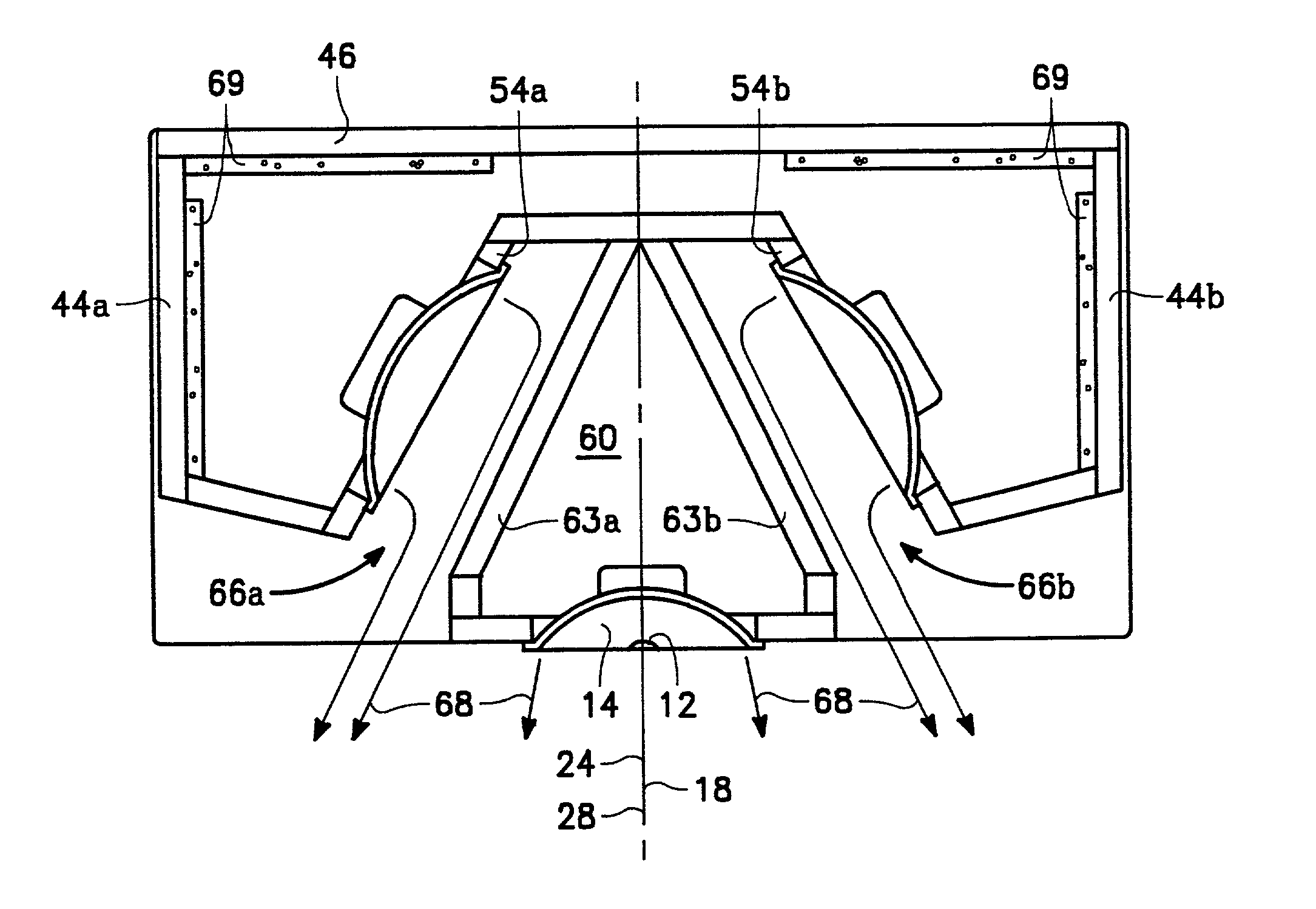
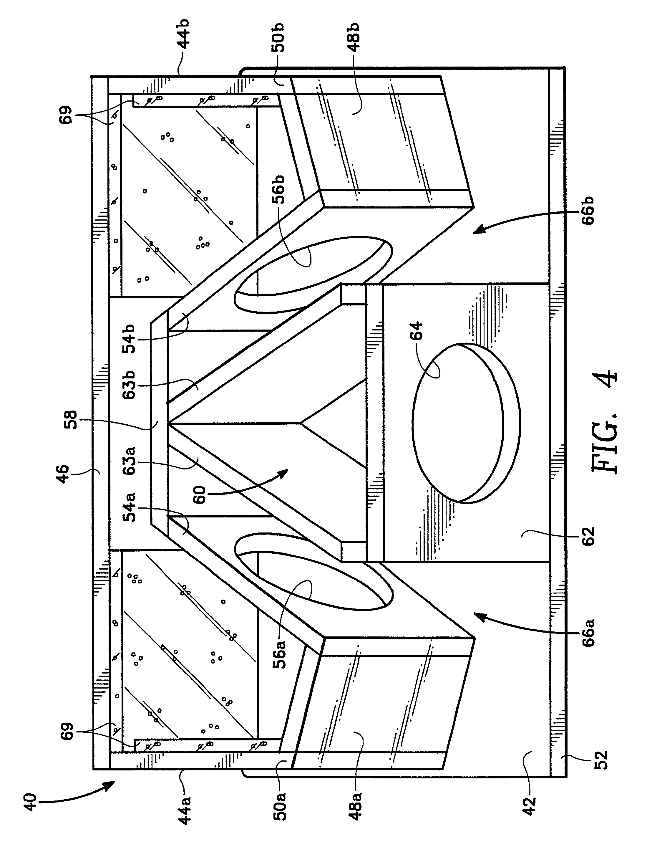
[0011]As stated above, the tweeter is mounted to the enclosure and emits its sound pattern directly outward from the speaker, and the woofer is mounted to the woofer support wall. The woofer, however, emits its low frequency sound pattern directly into the sound channel. From the sound channel, the low frequency sound pattern is reflected off the rear wall of the enclosure and is re-directed out of the speaker. Since the sound channel is symmetrically oriented around the tweeter, the effective low frequency sound pattern (the pattern that actually leaves the speaker) is also symmetrically oriented around the tweeter. Stated differently, the low frequency sound pattern has an effective center axis that is coincident, or co-axial, with the high frequency pattern center axis. This results in improved speaker performance over the entire audible frequency range, even if the listener is not positioned directly in front of the speaker.

Problems solved by technology

Specifically, the listener tends to get an increased concentration of low frequency response because the listener is no longer positioned symmetrically between the woofer outputs, and the overall signal that is received by the listener becomes distorted by the low-frequency component of the sound pattern.
In this arrangement, however, the woofer becomes limited in power-handling capabilities.
To address the power handling problem, another woofer is typically added, but this can sometimes become impractical, particularly when a small-size speaker is desired.

Method used


Image

  • Coincident source stereo speaker
  • Coincident source stereo speaker
  • Coincident source stereo speaker

Examples


Embodiment Construction

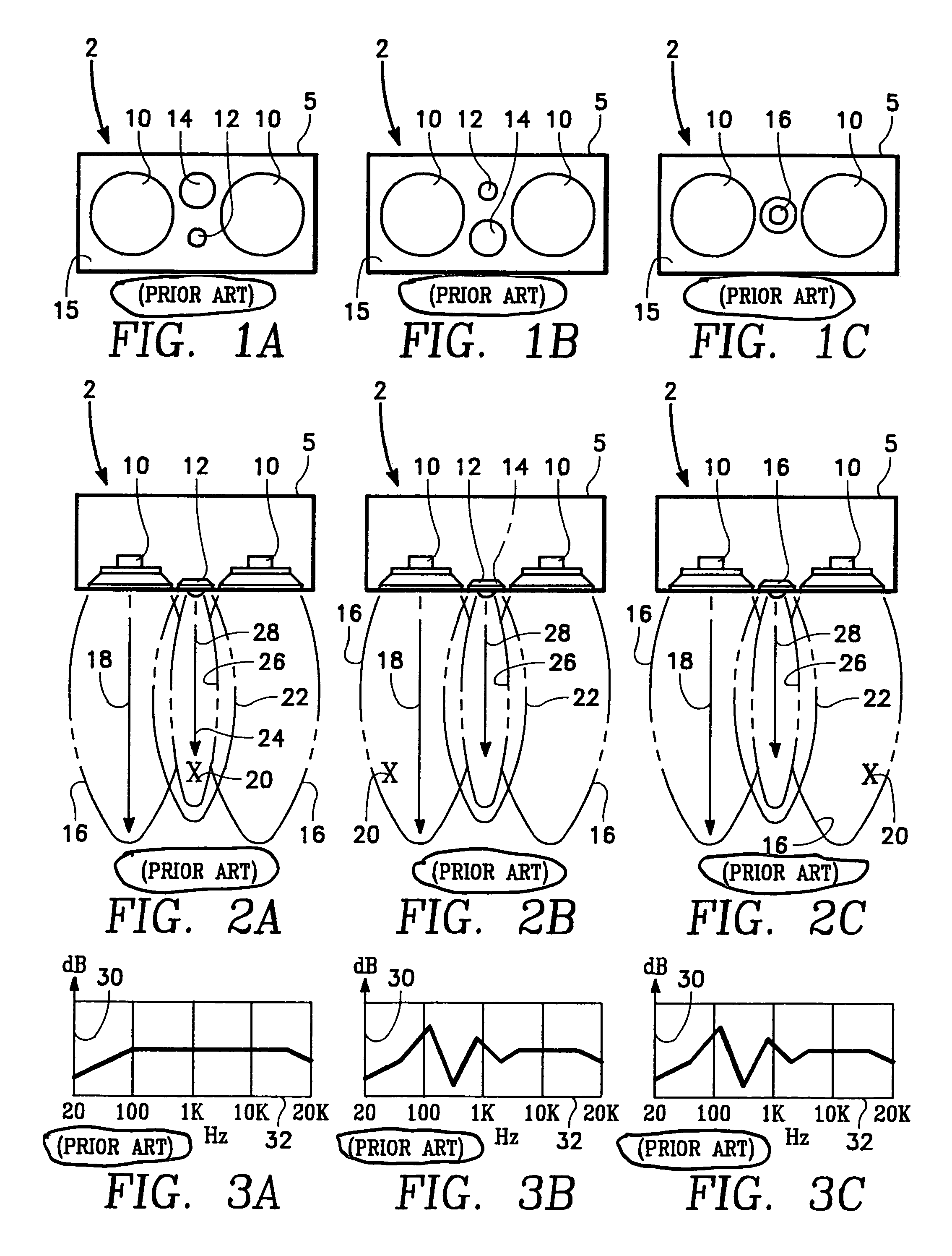
[0024]In overview, and referring initially to FIGS. 1A through 2C, prior art speakers are shown and generally designated by reference character 2. Each speaker 2 consists of a casing 5 that houses a pair of low-frequency components 10, or “woofers”, that are symmetrically arranged about a mounted mid-range component 14 and a high frequency component 12, or “tweeter”. Typically, the mid-range component and the tweeter are positioned in the center of speaker face 15, and the woofers are symmetrically arranged about the tweeter and mid-range component. In some instances, the tweeter and midrange components are co-axially mounted, see FIG. 1C, so that the center axis of the respective sound beams emanating therefrom is coincident, as described more fully below.

[0025]For the above prior art embodiment, and as shown in FIGS. 2A–2C, each woofer has a corresponding sound beam 16 that is centered around a low-frequency center axis 18. Similarly, the mid-range component 14 emits a mid-range s...


PUM


Abstract

A coincident source stereo speaker in accordance with the present invention includes a high-frequency component (tweeter) and a low-frequency component (woofer) that are separated by a sound channel. The tweeter emits a first sound pattern directly outward from the speaker, with the sound pattern having a corresponding high frequency center axis. The sound channel is located between the tweeter and woofer and is symmetrically oriented around the high-frequency component. The woofer emits a second sound pattern into the sound channel for re-direction out of the speaker. With this configuration, the second sound pattern has an effective low frequency center axis that is coincident with the high frequency center axis. As a result, the tweeter and woofer exhibit co-axial performance characteristics, even though they are not physically located co-axially.

Description

[0001]This application claims priority from Provisional Application Ser. No. 60 / 322,807, which was filed Sep. 14, 2001.FIELD OF THE INVENTION[0002]The present invention applies to loudspeakers. More particularly, the present invention applies to loudspeakers that are used in stereo systems. The present invention is particularly, but not exclusively, useful as a high performance speaker which has a uniform output over the entire audible frequency spectrum, even when the listener is not centered in front of the speaker, for increased listening enjoyment.BACKGROUND OF THE INVENTION[0003]Speakers are well-known in the prior art for providing the user with listening enjoyment of music. In particular, high-performance speakers cooperate with stereo systems to provide extreme clarity of various bass, mid-range and treble music components of the audible frequency spectrum. To do this, a high-performance speaker typically incorporates a woofer component, mid-range component and a tweeter com...

Claims


Application Information

Patent Timeline
IPC IPC(8): H04R25/00H04R1/26H04R5/02
CPCH04R1/26H04R5/02
Inventor VANDERSTEEN, RICHARD J.
Owner VANDERSTEEN RICHARD J
Learn More