Speaker and speaker module

a speaker module and speaker technology, applied in the direction of transducer casings/cabinets/supports, electrical devices, transducers, etc., can solve the problem that the module with a smaller size cannot provide enough space for mounting the fpcb, and achieve the effect of reducing the interference of the circuit board on the terminal antenna, increasing the operation space, and reducing the risk of operation

Active Publication Date: 2019-03-14
GOERTEK INC
View PDF0 Cites 0 Cited by
  • Summary
  • Abstract
  • Description
  • Claims
  • Application Information

AI Technical Summary

Benefits of technology

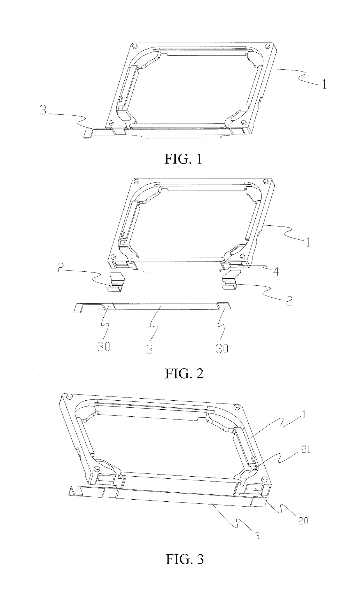
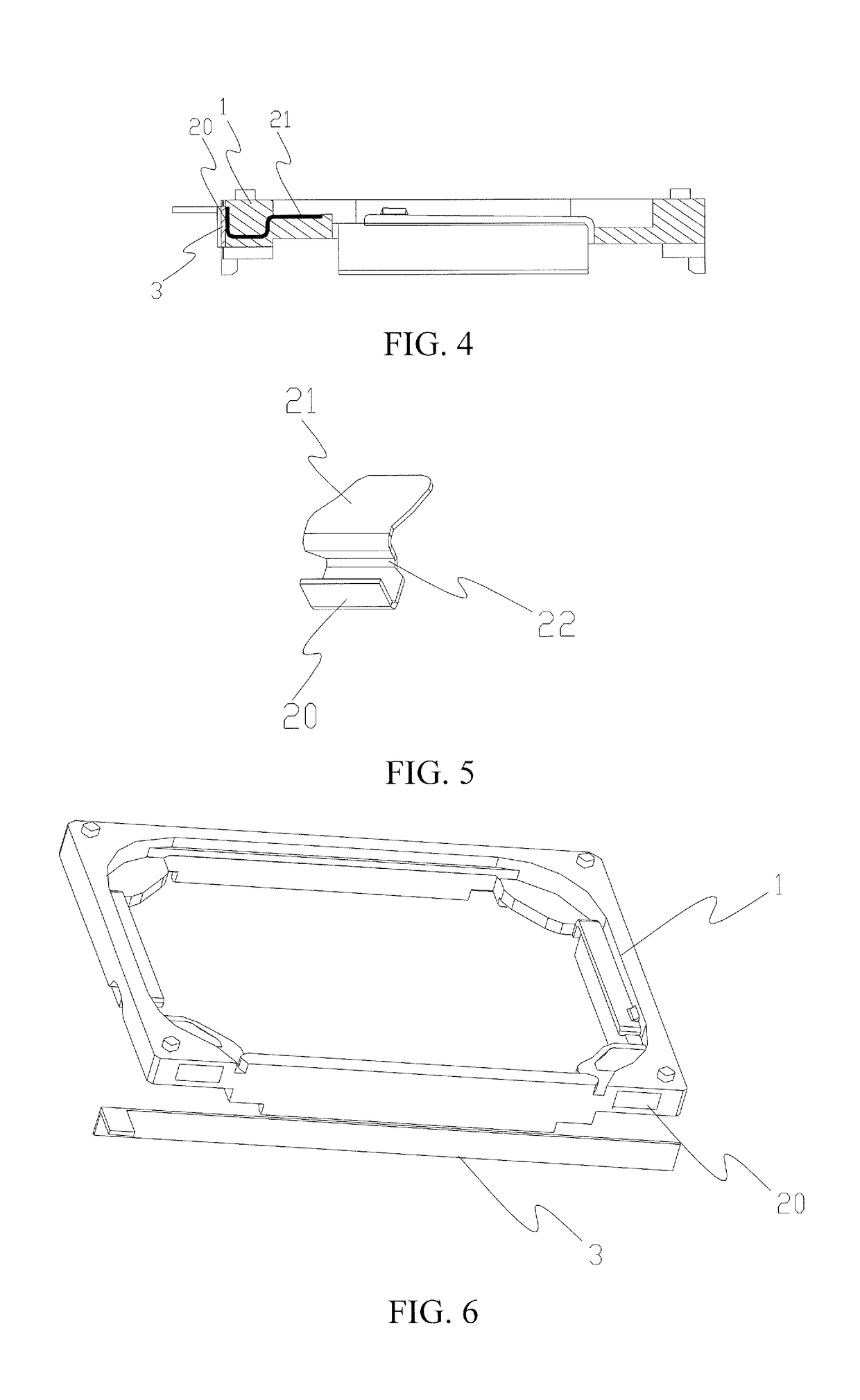
[0015]In the speaker provided by the present invention, the first pad portions exposed from the end surface of the housing are connected with the lead of the voice coil, and the second pad portions exposed from the side wall of the housing are connected with the circuit board, so that the voice coil and the circuit board are connected together. Through the connection structure provided by the present invention, the circuit board can be attached to the side wall of the housing, so that an operation space is increased, and an operation risk is reduced. By attaching the circuit board to the side wall of the housing, interference of the circuit board on a terminal antenna is reduced, and the possibility of the circuit board involving in vibration of a back chamber is reduced, so that the performance of the speaker is improved to some extent. Meanwhile, by providing the circuit board on the side wall of the housing, the shape of the circuit board is simplified, thus providing a compact layout, and accordingly saving costs.

Problems solved by technology

So, the module with a smaller size cannot provide enough space for mounting the FPCB.

Method used


Image

  • Speaker and speaker module
  • Speaker and speaker module
  • Speaker and speaker module

Examples


Embodiment Construction

[0026]Various exemplary embodiments of the present invention will now be described in detail with reference to the drawings. It should be noted that the relative arrangement of the components and steps, the numerical expressions, and numerical values set forth in these embodiments do not limit the scope of the present invention unless it is specifically stated otherwise.

[0027]The following description of at least one exemplary embodiment is merely illustrative in nature and is in no way intended to limit the present invention, its application, or uses.

[0028]Techniques and equipment as known by one of ordinary skill in the relevant art may not be discussed in detail but are intended to be part of the description where appropriate.

[0029]In all of the examples illustrated and discussed herein, any specific values should be interpreted to be illustrative only and non-limiting. Thus, other examples of the exemplary embodiments could have different values.

[0030]Notice that similar referen...


PUM


Abstract

The present invention relates to a speaker, and speaker module. The speaker comprises a housing and two electrical connection members mounted on the housing, each electrical connection member comprises a second pad portion exposed from a side wall of the housing, and the second pad portion is disposed in parallel to the side wall of the housing. The speaker further comprises a circuit board attached to the side wall of the housing, and the circuit board is electrically connected to the second pad portions. The speaker of the present invention enables attaching the circuit board to the side wall of the housing, thus increasing operation space, and reducing operational risks. By attaching the circuit board to the side wall of the housing, the present invention reduces interference of the circuit board on a terminal antenna, and reduces the possibility of the circuit board involving in vibration of a back chamber, thus improving the performance of the speaker. Meanwhile, by providing the circuit board on the side wall of the housing, the present invention simplifies the shape of the circuit board, thus providing a compact layout, and accordingly saving costs.

Description

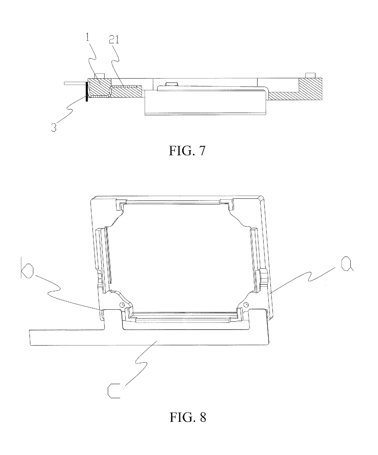
FIELD OF THE INVENTION[0001]The present invention relates to the field of sound producing devices, and more particularly, to a speaker. The present invention further relates to a speaker module.BACKGROUND OF THE INVENTION[0002]Speakers, as important acoustic components in electronic equipment, are transducing apparatus for converting electrical signals into sound signals. A speaker unit comprises a mounting housing, as well as a magnetic circuit assembly, a vibration assembly and other parts which are disposed in the mounting housing.[0003]Currently, pads of speaker units on the market are located in a Z-axis direction of products. Referring to FIG. 8, a speaker unit comprises a housing a and pads b disposed on the upper end surface of the housing a. Generally, there are two pads b. The two pads b are distributed in the length direction or the width direction of the unit. In this way, an FPCB (Flexible Printed Circuit Board) c connected with the speaker unit will need a larger mount...

Claims


Application Information

Patent Timeline
Patent Type & Authority Applications(United States)
IPC IPC(8): H04R1/02H04R9/02H04R9/04
CPCH04R1/025H04R9/025H04R9/045H04R9/02H04R9/06H04R2400/11H04R1/06
Inventor YANG, FANMIAO, QING
Owner GOERTEK INC
Why Eureka
Try Eureka