
Low-frequency spiral waveguide speaker

a waveguide speaker and low-frequency technology, applied in the direction of transducer details, electrical transducers, electrical apparatus, etc., can solve the problems of high noise, large and heavy speaker systems, and many poor sound quality of these speaker systems, so as to reduce tuning frequency and improve speaker performance.

Active Publication Date: 2021-01-14
ALLISON CLAY
View PDF0 Cites 2 Cited by
  • Summary
  • Abstract
  • Description
  • Claims
  • Application Information

AI Technical Summary

Benefits of technology

The present invention provides a portable speaker system that is lightweight, compact, and has good-sounding quality by minimizing the negative effects of group delay. The system includes a low-frequency spiral waveguide, which offers superior sonic qualities and a compact form. The spiral waveguide helps to maintain a constant direction for the soundwave and provides a longer effective acoustic length with minimum pressure attenuation. This results in improved efficiency for a low-frequency transducer and reduced unwanted by-products. In summary, the invention provides a high-quality portable speaker system that is easy to carry and use.

Problems solved by technology

However, the sound quality of many of these speaker systems, particularly in the low-frequency range, leaves much to be desired.
Thus, in order to achieve high-qualify low-frequency sound, a large and heavy speaker system is often required.

Method used


Image

  • Low-frequency spiral waveguide speaker
  • Low-frequency spiral waveguide speaker
  • Low-frequency spiral waveguide speaker

Examples


Embodiment Construction

[0029]For purposes of promoting and understanding of the principles of the invention, reference will now be made to the embodiments illustrated in the drawings and specific language will be used to describe the same. It will nevertheless be understood that no limitation of the scope of the invention is thereby intended. The invention includes any alterations and further modifications in the illustrated devices and described methods and further applications of the principles of the invention that would normally occur to one skilled in the art to which the invention relates.

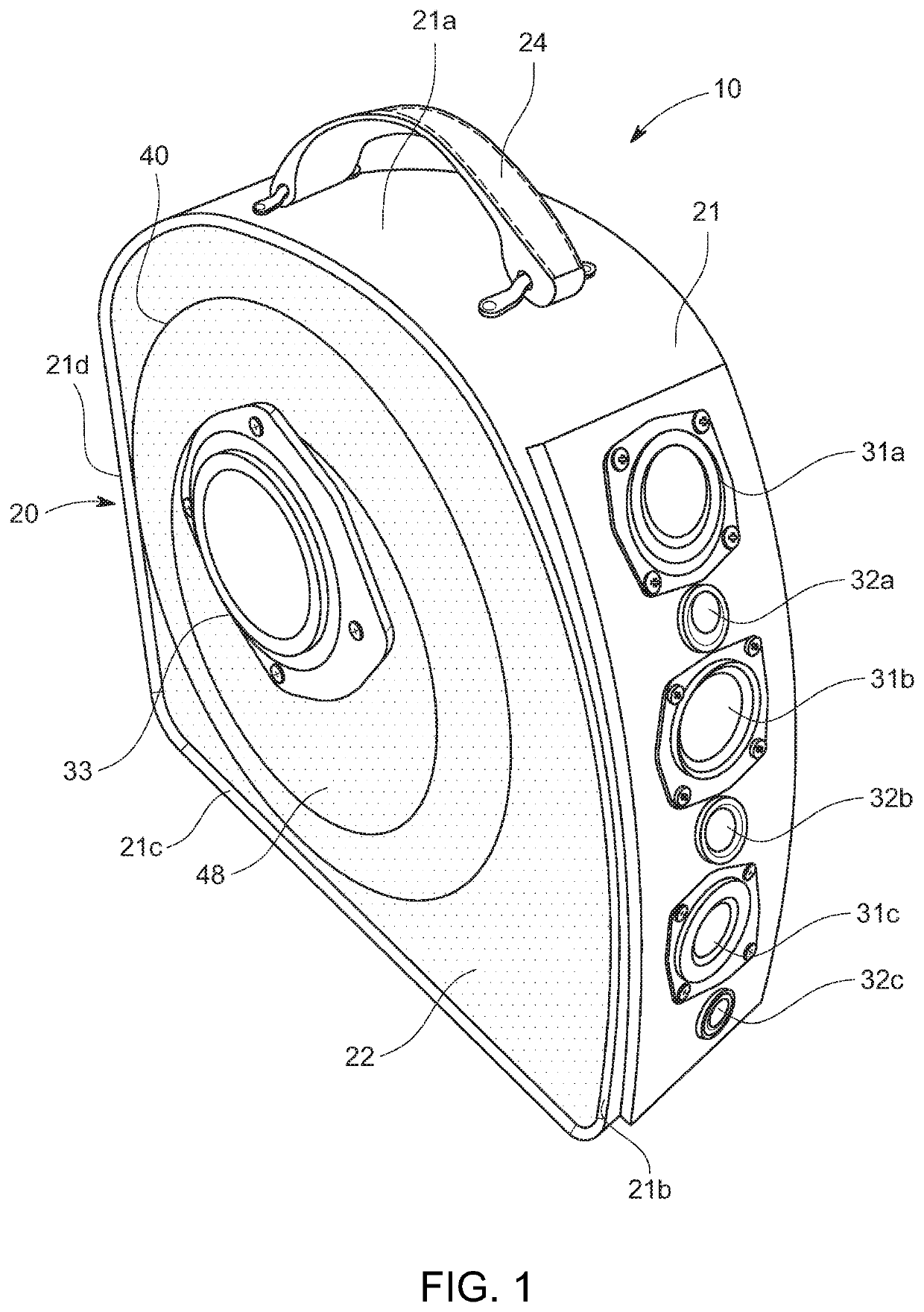
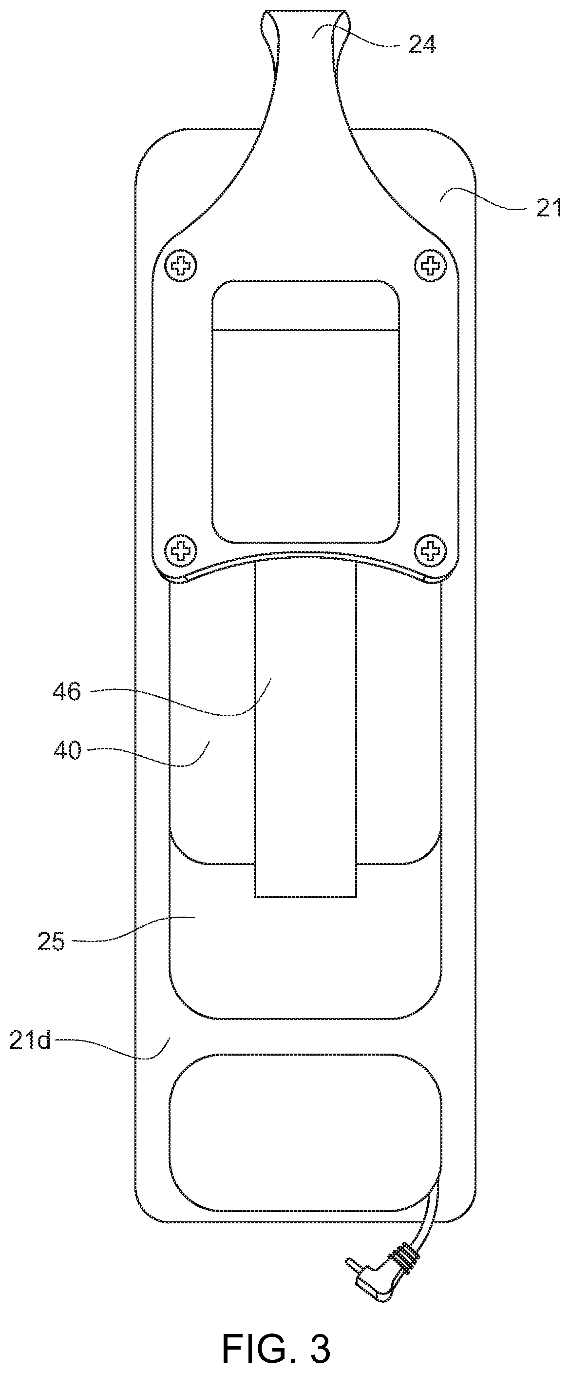
[0030]As best shown in FIG. 1-FIG. 6, one presently preferred embodiment of the invention comprises a speaker system 10 having a housing 20 which includes a curved sidewall 21 and flat end panels 22, 23. A handle 24 may be provided on a top region 21a of the sidewall 21 to allow the speaker 10 to be easily transported. A front region 21b of the sidewall may include a speaker array 30 that may include one or more sp...


PUM


Abstract

A low-frequency loudspeaker is provided comprising an enclosure having a front, a back and a sidewall. An audio speaker is mounted in an opening in the front of the enclosure. The audio speaker has a diaphragm for producing front sound waves that are transmitted outwardly from the diaphragm and back sound waves that are transmitted into the enclosure from the diaphragm. A spiral waveguide is positioned within the enclosure. The spiral waveguide has a first end proximal to the speaker diaphragm for receiving the back sound waves and extends outwardly therefrom in a spiral pattern to a second end that forms a low-frequency terminus exit port opening in the sidewall.

Description

BACKGROUND OF THE INVENTIONField of the Invention[0001]The present invention relates to the reproduction of sound in the low frequency region. More specifically, a more compact method of constructing what is commonly referred to as a transmission line loudspeaker.Description of the Related Art[0002]With the advent of wireless technologies such as Bluetooth, there has been a marked increase in the use of portable, wireless speakers for a variety of uses. However, the sound quality of many of these speaker systems, particularly in the low-frequency range, leaves much to be desired. Traditional subwoofers that are designed to produce sound in the low frequency range require large-coned speakers and / or large heavy boxes to achieve the desired low frequencies. Thus, in order to achieve high-qualify low-frequency sound, a large and heavy speaker system is often required.[0003]Accordingly, there is a need for a light-weight, compact, portable speaker system that does not sacrifice sound qu...

Claims


Application Information

Patent Timeline
Patent Type & Authority Applications(United States)
IPC IPC(8): H04R1/02
CPCH04R1/02H04R1/26H04R1/2853H04R1/2888
Inventor ALLISON, CLAY
Owner ALLISON CLAY
Learn More