
Adaptive transmission system

a transmission system and adaptive technology, applied in power management, wireless communication, channel coding adaptation, etc., can solve the problems of reducing the transmission capacity of communications satellites, affecting the transmission efficiency of communications satellites, etc., to achieve the effect of reducing undesirable aspects

Active Publication Date: 2006-05-16
DIRECTV LLC
View PDF39 Cites 74 Cited by
  • Summary
  • Abstract
  • Description
  • Claims
  • Application Information

AI Technical Summary

Benefits of technology

[0010]The method comprises the steps of receiving information describing a time-varying deleterious propagation characteristic of the transmission signal to the terrestrial region; generating the transmission signal having a transmission characteristic which mitigates the undesirable aspects of the time-varying propagation characteristic; and transmitting th

Problems solved by technology

Unfortunately, at the wavelengths typically used in satellite-to-home television broadcasts, rain and other sources of atmospheric attenuation have a significant effect upon the CNR.
Hence, during heavy rain, some customers can experience degraded signal quality.
Unfortunately, the amount of attenuation from rain and similar atmospheric parameters can be substantial and widely varying.
Increasing transmitter power on a communications satellite may be economically impractical or even technologically infeasible.
Satellites have severe limitations on weight which can be delivered at desired orbital locations due to launch vehicle costs and other limitations.
This weight limitation constrains the size of solar panels, the charge capabilities of the on-board batteries, and the physical size of the transmitter and related electronics.
Furthermore, one type of transmitter, the traveling wave tube amplifier (TWT) has upper power limits for reliable operation.

Method used


Image

  • Adaptive transmission system
  • Adaptive transmission system
  • Adaptive transmission system

Examples


Embodiment Construction

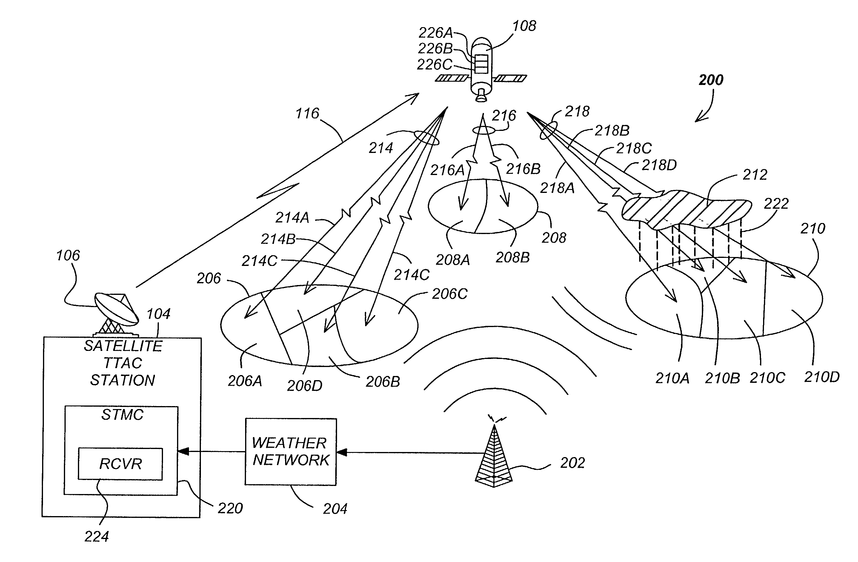
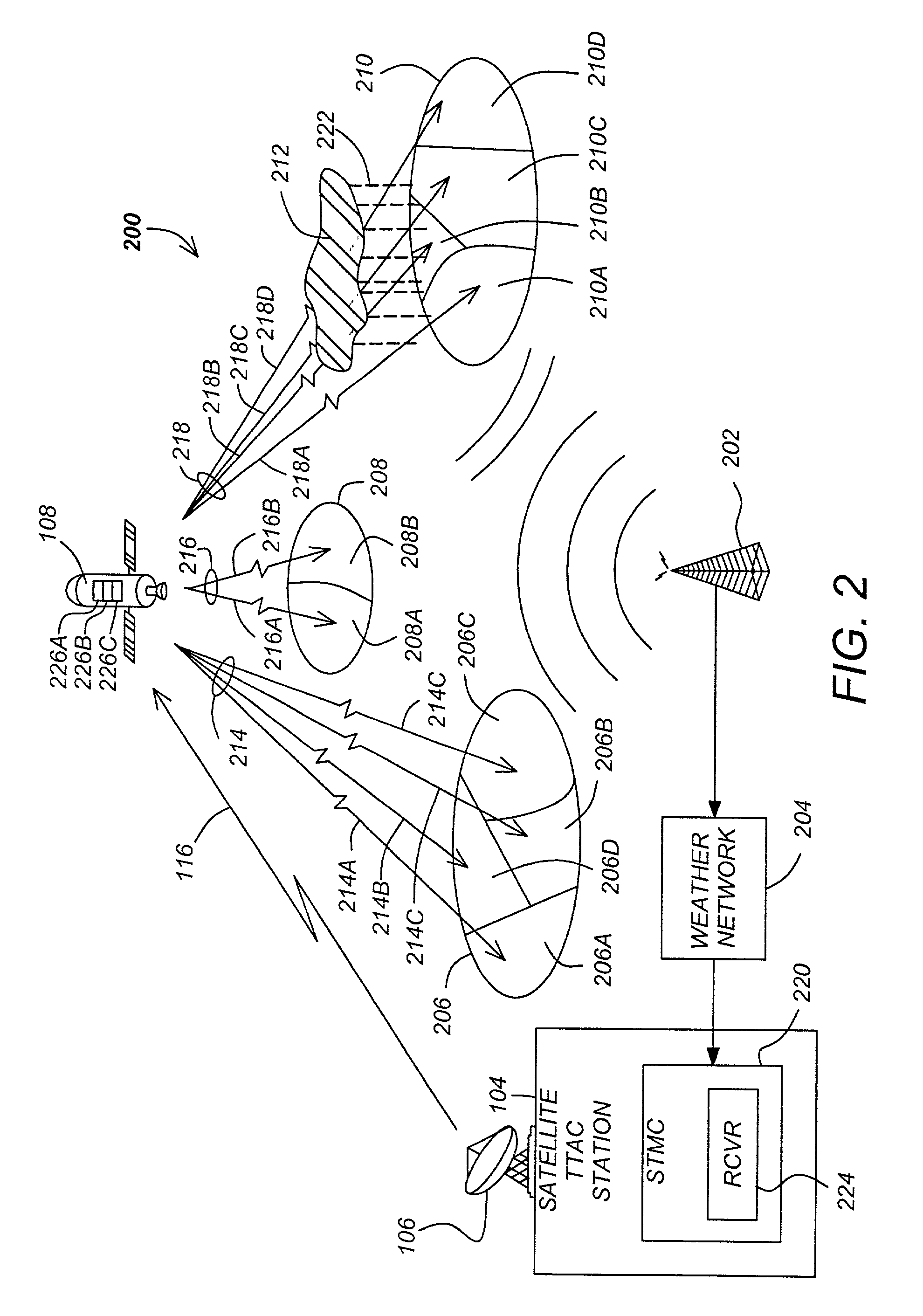
[0020]In the following description, reference is made to the accompanying drawings which form a part hereof, and which is shown, by way of illustration, several embodiments of the present invention. It is understood that other embodiments may be utilized and structural changes may be made without departing from the scope of the present invention.

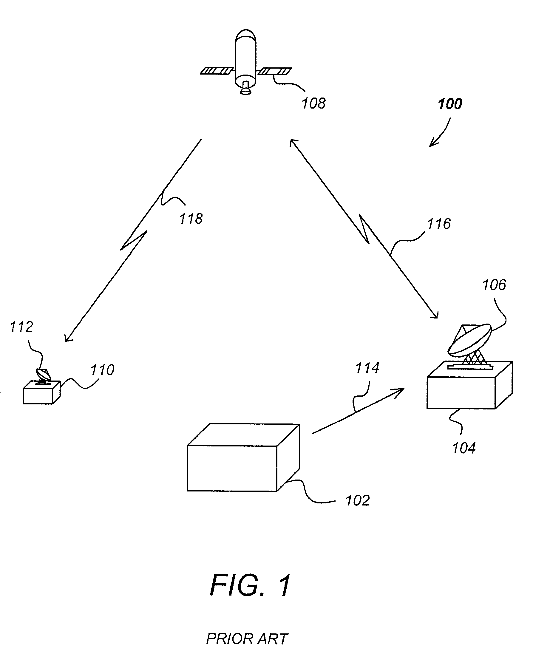
[0021]FIG. 1 is a diagram illustrating an overview of a multi-channel video distribution system 100. The video distribution system 100 comprises an uplink center 104, a satellite 108, a terrestrial receiver 112 and a subscriber 110.

[0022]The uplink center 104 receives program material from external sources 102 via a communications link 114, and using an uplink antenna 106, transmits the program material and program control information to the satellite 108 via uplink 116. The satellite receives and transmits the video programs and control information to the subscriber via downlink transmission signal 118. The subscriber 110 receives this info...


PUM


Abstract

A method, apparatus, article of manufacture, and a computer memory structure adaptively controlling a transmission signal from a satellite to at least one terrestrial receiver in a terrestrial region is disclosed. The method comprises the steps of receiving information describing a deleterious time-varying propagation characteristic of the transmission signal to the terrestrial region; generating the transmission signal having a transmission characteristic which mitigates the undesirable aspects of the time-varying propagation characteristic; and transmitting the generated transmission signal from the satellite to the terrestrial receiver. The article of manufacture comprises a controller device tangibly embodying instructions to perform the method steps described above. The apparatus comprises a receiver for receiving information describing a time-varying signal propagation characteristic of the signal to the terrestrial region; a signal generator for adaptively generating a transmission signal having a transmission characteristic mitigating the propagation characteristic; and a transmitter for transmitting the generated transmission signal.

Description

BACKGROUND OF THE INVENTION[0001]1. Field of the Invention[0002]This invention relates to systems and methods for improving a power and bandwidth constrained transmission system, and in particular to a system and method for adaptively varying the transmission signal according to measured or predicted time-varying signal propagation characteristics.[0003]2. Description of the Related Art[0004]A typical communications system, whether terrestrial or satellite-based, is constrained in its transmission power and signal bandwidth. The communications system may also be required to deliver reliable communications to one point, as in a terrestrial microwave link, or to many points in a satellite broadcast system serving the United States.[0005]A typical satellite communications system servicing a large geographical region such as the United States is typically designed such that all signals transmitted to terrestrially based receivers have a minimum carrier to noise ratio (CNR) when received...

Claims


Application Information

Patent Timeline
IPC IPC(8): H04B15/00H04B7/01
CPCH04B7/18513H04L1/0003H04L1/0017H04L1/0009H04W52/24
Inventor GODWIN, JOHN P.LONER, PATRICK J.WILLIAMS, JIM C.
Owner DIRECTV LLC
Learn More