Ball-lock insert assemblies

a technology of ball-locking and inserts, which is applied in the field of tool retainers for punch presses, can solve the problems of workpiece deformation surfaces of punches and die wear after repeated us

Inactive Publication Date: 2006-05-30
WILSON TOOL INT
View PDF59 Cites 32 Cited by
  • Summary
  • Abstract
  • Description
  • Claims
  • Application Information

AI Technical Summary

Problems solved by technology

For example, the workpiece-deforming surfaces o

Method used


Image

  • Ball-lock insert assemblies
  • Ball-lock insert assemblies
  • Ball-lock insert assemblies

Examples


Embodiment Construction

[0040]The following detailed description is to be read with reference to the drawings, in which like elements in different drawings have been given like reference numerals. The drawings, which are not necessarily to scale, depict selected embodiments and are not intended to limit the scope of the invention.

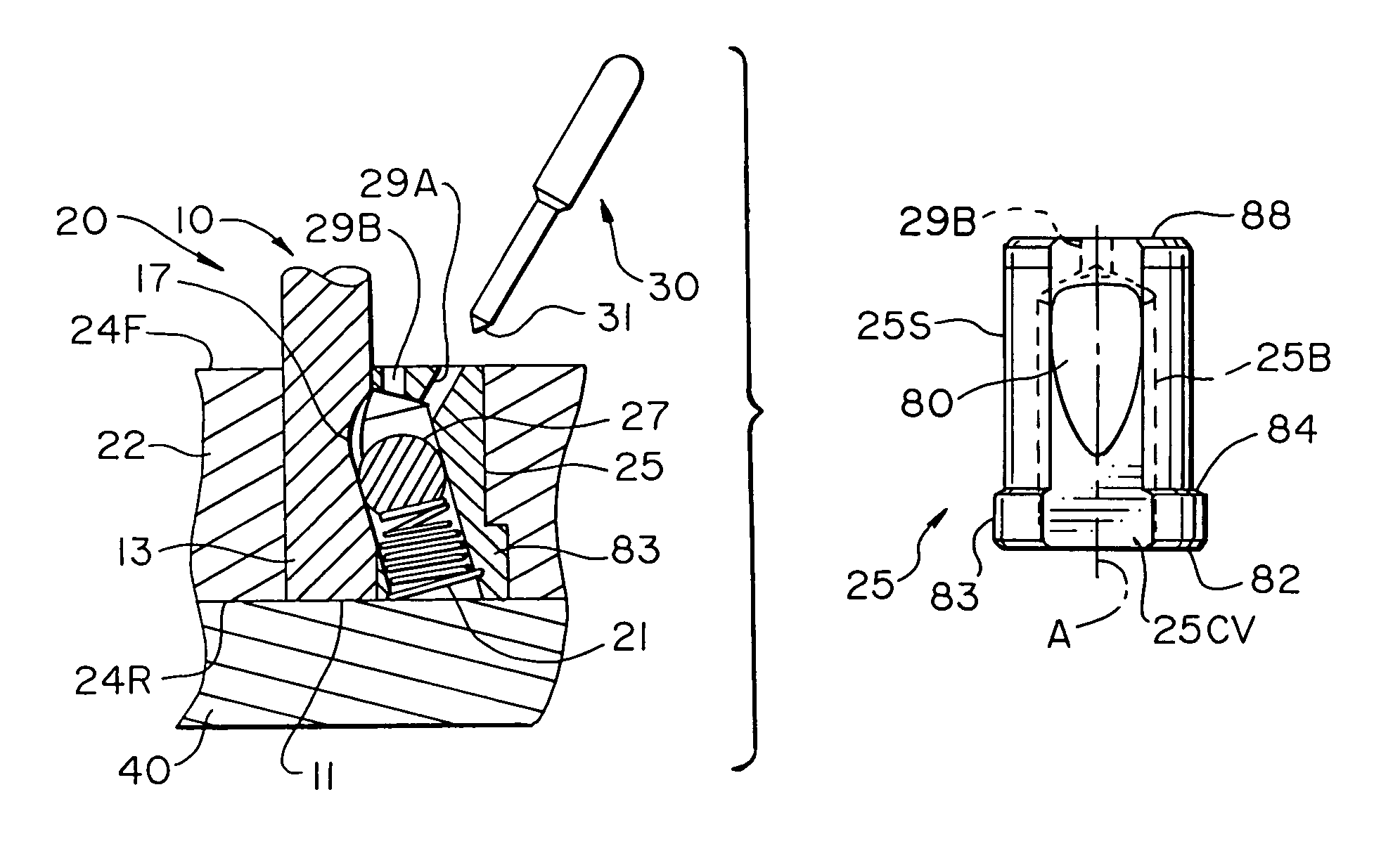
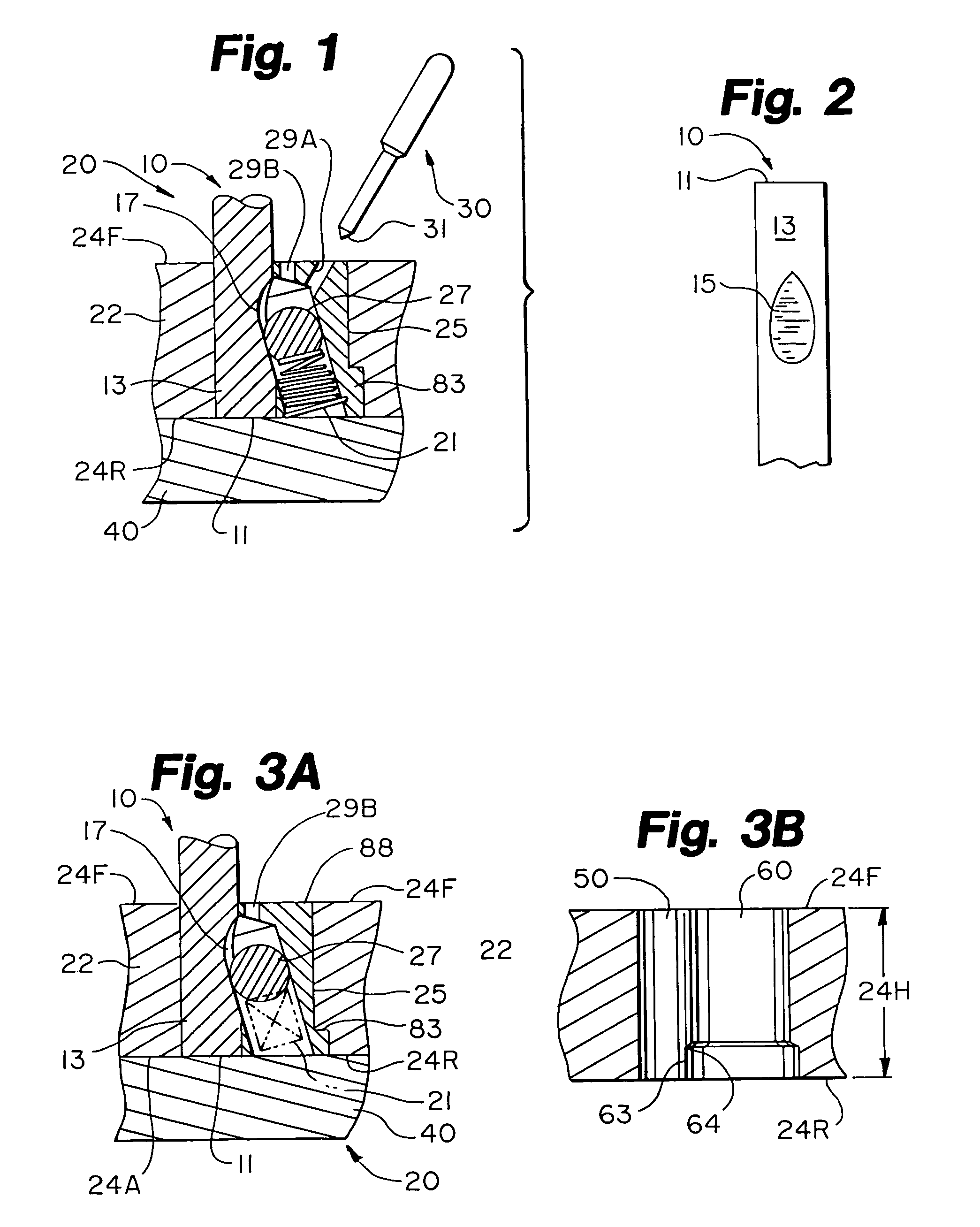
[0041]FIG. 1 illustrates one embodiment of the present invention, wherein there is provided a tool 10, a retainer assembly 20, and a removal tool 30. The retainer assembly 20 is adapted to removably retain the tool 10 in its operative position (depicted in FIG. 1). The tool 10 may be a punch, a die, or the like. In its operative position, the tool 10 is adapted to perform a punching or forming operation upon a workpiece (e.g., a piece of sheet metal). Skilled artisans are quite familiar with the configuration of complimentary punches and dies, as well as with the proper placement and machining of workpieces therebetween.

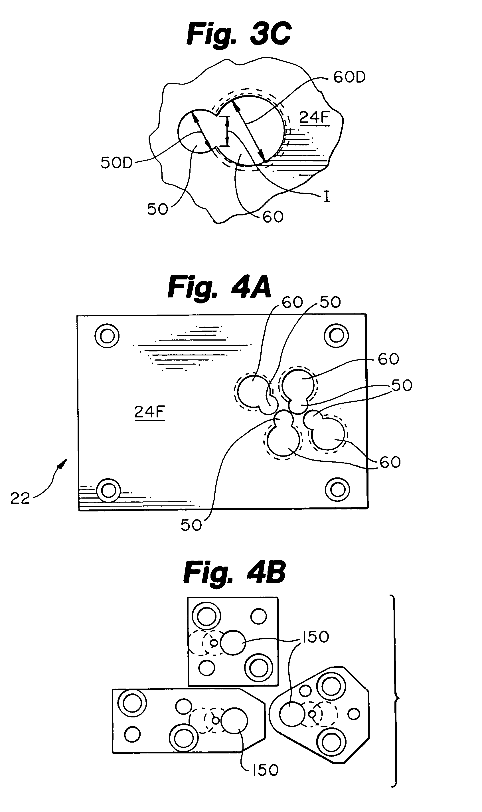
[0042]The retainer assembly 20 includes a holder plate 22 to ...


PUM

PropertyMeasurementUnit
Angleaaaaaaaaaa
Angleaaaaaaaaaa
Lengthaaaaaaaaaa

Abstract

The invention provides a ball-lock insert assembly adapted to be mounted axially in a mount opening formed in a holder plate having a desired thickness. The ball-lock insert assembly comprises an insert body having an axis and an elongated interior recess extending at an angle relative to this axis. The elongated interior recess is configured to house a resiliently-biased engagement member. The invention also provides retainer assemblies that include ball-lock assemblies, as well as methods of producing retainer assemblies, which methods include providing ball-lock assemblies.

Description

CROSS REFERENCE TO RELATED APPLICATIONS[0001]The present application is a divisional of patent application having U.S. Ser. No. 10 / 071,888, filed Feb. 8, 2002 U.S. Pat. No. 6,755,103, the entire disclosure of which is incorporated herein by reference.FIELD OF THE INVENTION[0002]The present invention relates to punch presses. More particularly, this invention relates to tool retainers for punch presses.BACKGROUND OF THE INVENTION[0003]Tool retainers for punch presses are well known in the art. Typically, the retainer is a metal block that carries a tool (e.g., a punch or die). The tool held by the retainer normally extends away from the retainer block toward a workpiece (e.g., a piece of sheet metal) to be punched or formed. The retainer block is usually secured to a mounting plate of the punch press. Thus, the retainer block interconnects the tool and the press, and enables the tool to be accurately positioned.[0004]Tool retainers are preferably adapted to carry tools in a removable...

Claims


Application Information

Patent Timeline
IPC IPC(8): B26D7/26B21D28/34
CPCB21D28/34B26D7/2614Y10T279/17761Y10T279/17196Y10T83/04Y10T83/944Y10T83/9473Y10T83/9457Y10T83/9476Y10T83/9423Y10T83/9461Y10T83/2159
Inventor MOREHEAD, JOHN H.
Owner WILSON TOOL INT
Why Eureka
Try Eureka