Multi-function luminaire

a multi-functional, luminaire technology, applied in the direction of luminescence, lighting and heating apparatus, light source combinations, etc., can solve the problems of poor color rendition and low quality status, difficult dimming of the circline, and more fixture design challenges, and achieve excellent color rendition

Inactive Publication Date: 2006-05-30
LAU KENNETH H
View PDF5 Cites 54 Cited by
  • Summary
  • Abstract
  • Description
  • Claims
  • Application Information

AI Technical Summary

Benefits of technology

[0006]The multi-function, multi-head lighting fixture will have the following features: instant on CFL and Circline dimmable features utilizing the latest energy saving CFL technology. CFL lamp life is 12,000 hours compared to incandescent lamp life of 750 hours. CFL lamps also last 16 times longer than incandescent lamps. Lamp color temperature is 2700 Kelvin CRI with a CRI of approximately 82 which gives warm color and excellent color rendition. The CFL will be driven by electronic ballast which only weigh a fraction of the old core coil ballast and it is available in miniature sizes to fit into the limited housing space. LED's will have their own power supply within the fixture housing.

Problems solved by technology

Circline lamps in their designs for residential applications because they relate fluorescent lamps to poor color rendition and low quality status as compared to halogen and incandescent lamps.
Circline are difficult to dim as they need special electronic ballasts and dimmers unlike incandescent and halogen lamps which do not.
Present day Internet households further cause more fixture design challenges for use with computer screens, TV monitors, Video. Display. Units (VDU's) and other visual tasks.

Method used


Image

  • Multi-function luminaire
  • Multi-function luminaire
  • Multi-function luminaire

Examples


Embodiment Construction

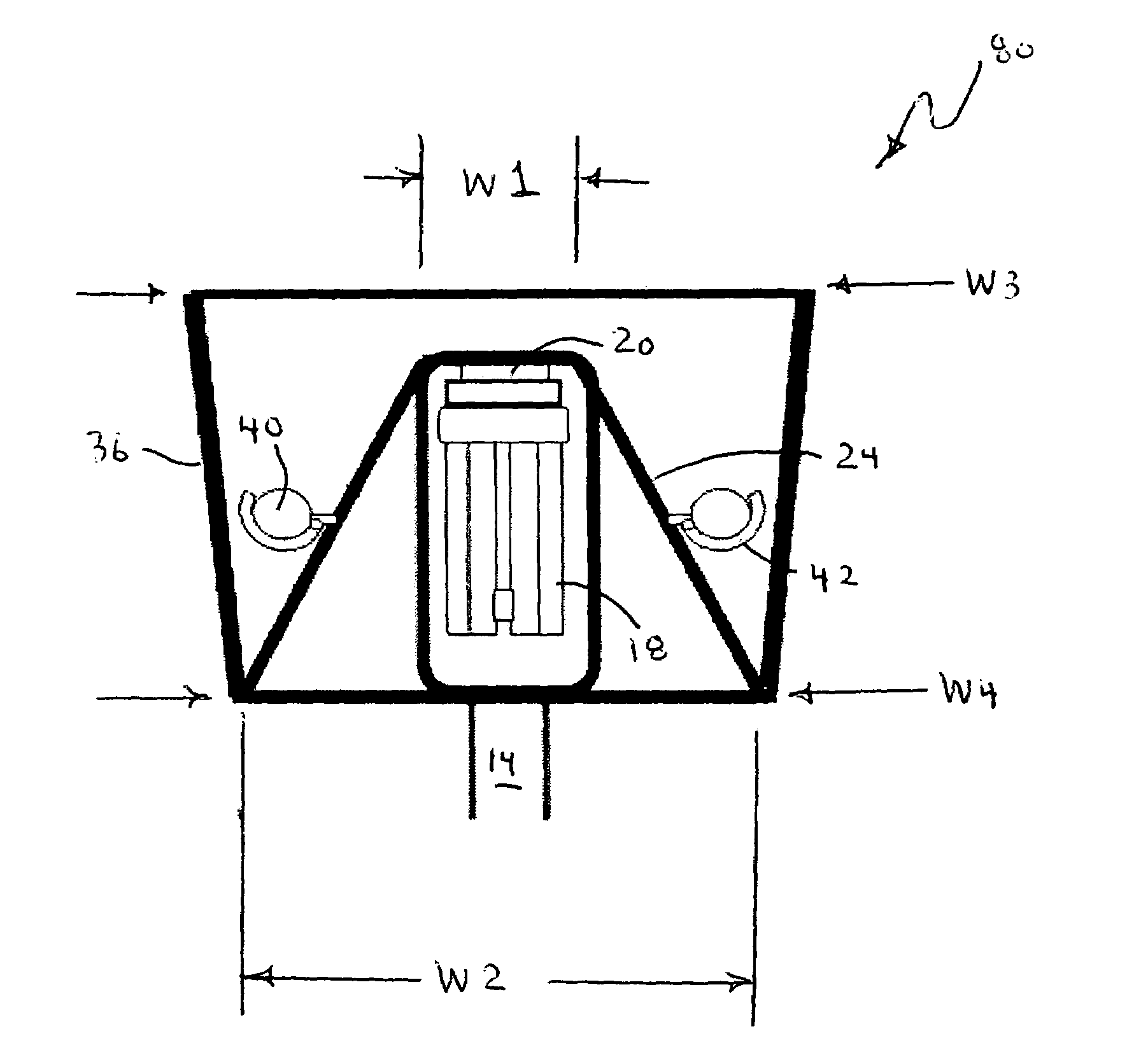
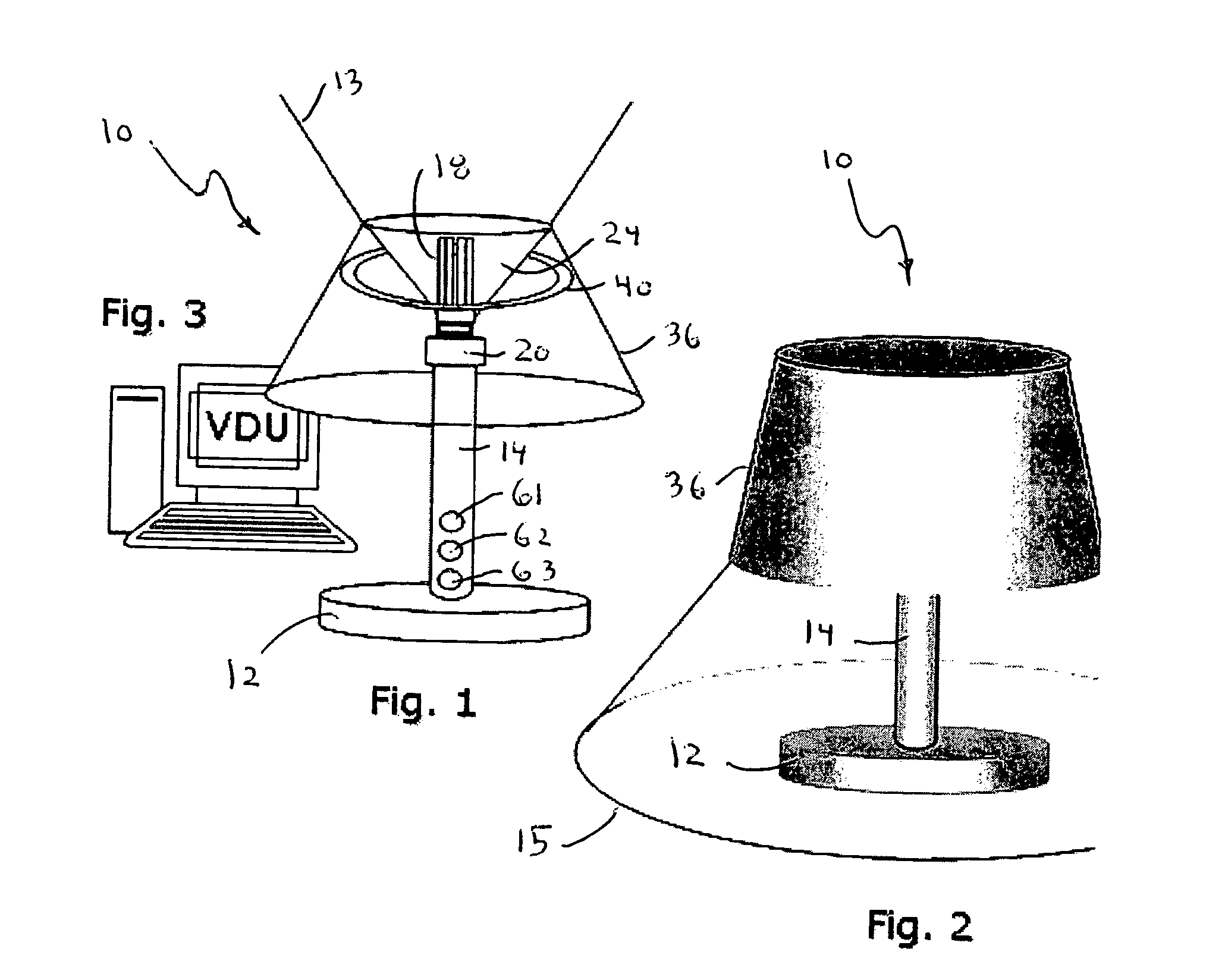
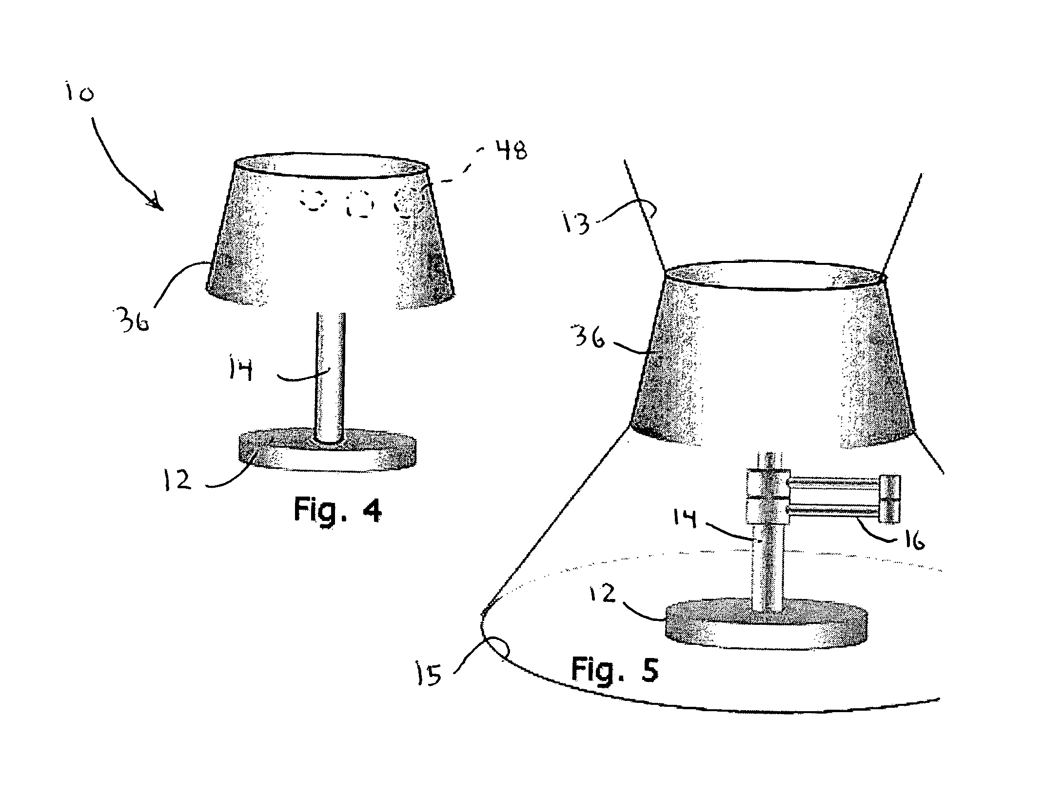
[0016]A first multi-function lighting fixture will now be described by referring to FIGS. 1–7 of the drawings. The lighting fixture is generally designated numeral 10. It has a base 12 and a post member 14 that function as support structure for a lamp such as a CFL lamp. FIG. 5 illustrates that the post member 14 may have a flexible arm assembly 16. FIG. 1 shows the upwardly directed light beam 13 and FIG. 2 shows the downwardly directed light beam 15.

[0017]The CFL lamp 18 is detachably threaded into electrical socket 20 mounted on post member 14. An inverted cone shaped shield 24 has a top edge 26 and a bottom edge 28. Top edge 26 has a width W1 and bottom edge 28 has a width W2. Shield 24 would normally be made of opaque material and preferably has a reflective inner surface and a reflective outer surface. The outer surface of shield 24 may have predetermined areas having non-reflective or baffle members 30 to provide light beam control. The shield 24 defines an interior zone 25 i...


PUM


Abstract

A multiple function lighting fixture that uses compact fluorescent lamps (CFL), and circular fluorescent lamps positioned in strategic locations inside a lampshade. A shield within the lampshade divides the area into a primary interior zone and a secondary interior zone. One of the respective lamps is located in each of the respective interior zones. One of the lamps provides for upwardly directed light and the other lamp provides downwardly directed light. The inner and outer surfaces of the shield may have reflective properties. The lampshade may have portions thereof having light transmitting properties. The inner surface of the lampshade may have reflective properties in some areas. LEDs may be mounted in various areas of the respective primary interior zone and secondary interior zones. The light fixture may also have dimmer control switches/sensors and there may be sensors for remote control operation for turning the respective lamps on and off.

Description

[0001]This patent application claims the priority of U.S. Provisional Patent Application. No. 60 / 365,729 filed Apr. 26, 2003.BACKGROUND OF THE INVENTION[0002]Architects and interior designers are reluctant to use CFL's or. Circline lamps in their designs for residential applications because they relate fluorescent lamps to poor color rendition and low quality status as compared to halogen and incandescent lamps. Dimming is also an important feature to have in residential lighting. The CFL and. Circline are difficult to dim as they need special electronic ballasts and dimmers unlike incandescent and halogen lamps which do not. Present day Internet households further cause more fixture design challenges for use with computer screens, TV monitors, Video. Display. Units (VDU's) and other visual tasks.[0003]It is an object of the invention to provide a novel multi-function lighting fixture using various types of energy efficient lamps.[0004]It is another object of the invention to provid...

Claims


Application Information

Patent Timeline
Patent Type & Authority Patents(United States)
IPC IPC(8): F21K2/00
CPCF21S6/002F21S6/005F21V7/0016F21Y2113/02F21Y2103/022F21Y2103/025F21Y2101/02F21Y2103/33F21Y2103/37F21Y2113/20F21Y2115/10
Inventor LAU, KENNETH H.
Owner LAU KENNETH H
Why Eureka
Try Eureka