Electroluminescent device with enhanced color rendition

a technology of color rendition and electroluminescent device, which is applied in the direction of discharge tube/lamp details, luminescent screen, discharge tube/lamp details, etc., can solve the problems of inferior color reproducibility to the case of observation under the conventional planar light source, fluorescent lamp, inferior color rendition to other white light sources, etc., and achieve excellent color rendition and color reproduction. excellent

Inactive Publication Date: 2010-10-19
FUJIFILM HLDG CORP +1
View PDF24 Cites 9 Cited by
  • Summary
  • Abstract
  • Description
  • Claims
  • Application Information

AI Technical Summary

Benefits of technology

[0007]An object of the invention is to provide an electroluminescent device excellent in color rendition. In particular, the invention is to provide an electroluminescent device emitting white light with such a luminescent intensity distribution (i.e., luminescent waveform) that exhibits excellent color rendition.
[0022]In the EL device of the invention having two luminescent local maxima, as described above, a first luminescent local maximum (hereinafter, sometimes referred to as a short-wavelength maximum) is in a range of from 450 to 530 nm, and a second luminescent local maximum (hereinafter, sometimes referred to as a long-wavelength maximum) is in a range of 605 nm or more, so as to realize visually white light emission excellent in color rendition.
[0024]It is preferred in the EL device of the invention that the long-wavelength maximum is in a range of from 605 to 615 nm. In the case where the long-wavelength maximum is in the range, better color rendition can be obtained.
[0025]It is preferred that the short-wavelength maximum is in a range of from 477 to 498 nm, and more preferably from 483 to 493 nm. In the case where the short-wavelength maximum is in a range of from 477 to 498 nm (more preferably from 483 to 493 nm), which is in the vicinity of 487 nm as the equilibrium point of G and B colors, the equability of the intensities of G and B colors can be further ensured to provide better color rendition. The equilibrium point of G and B colors (487 nm) herein is a point at which two colors of G and B are visually balanced upon considering G and B colors, and humans strongly sense green color on the long-wavelength side of the point and strongly sense blue color on the short-wavelength side of the point.
[0026]It is preferred that the EL device of the invention has a luminescent local minimum in a range of from 565 to 583 nm, and more preferably from 571 to 583 nm. In the case where the luminescent local minimum is in a range of from 565 to 583 nm (more preferably from 571 to 583 nm), which is in the vicinity of 578 nm as the equilibrium point of R and G colors, the R color (the waveform of the long-wavelength maximum) and the G and B colors (the waveform of the short-wavelength maximum) are separated from each other to provide better color rendition. The equilibrium point of R and G colors (578 nm) herein is a point at which two colors of R and G are visually balanced upon considering R and G colors, and humans strongly sense red color on the long-wavelength side of the point and strongly sense green color on the short-wavelength side of the point.

Problems solved by technology

The white dispersion EL element has various advantages as a flexible planar light source as having been described, but involves a problem where the color rendition thereof is inferior to the other white light sources, such as a fluorescent lamp.
For example, in the case where a transparent medium, such as a transparent positive image, is observed on the dispersion EL element, the color reproducibility is inferior to the case where it is observed under the conventional planar light source, such as a fluorescent lamp.

Method used


Image

  • Electroluminescent device with enhanced color rendition
  • Electroluminescent device with enhanced color rendition

Examples


example 1

Production Example 1 of EL Device of the Invention

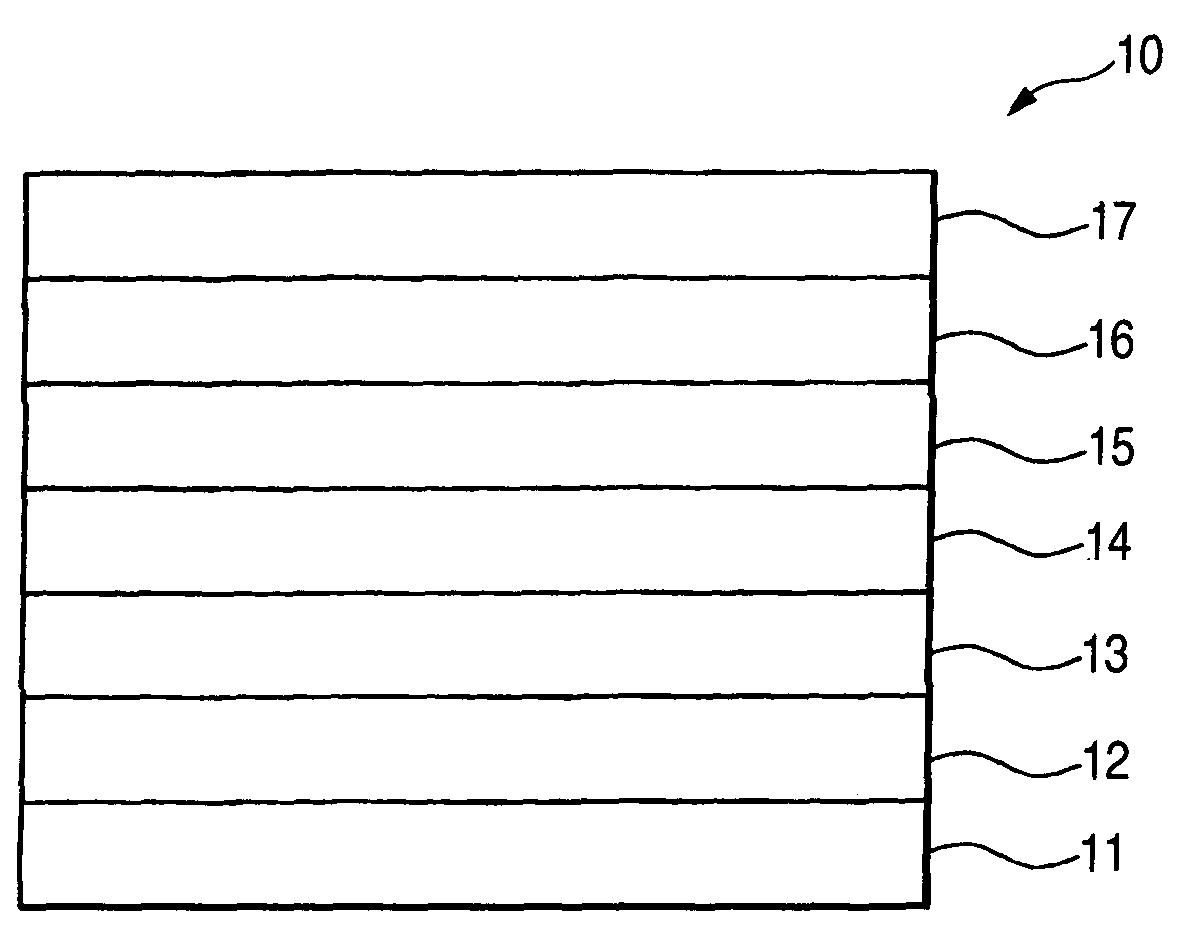
[0072]Zinc sulfide particles activated with copper and chlorine having a luminescent local maximum at 498 nm and an average particle diameter of 15 μm were mixed with and dispersed in a 30% by weight cyanoethyl cellulose solution (CR-S, produced by Shin-Etsu Chemical Co., Ltd., hereinafter the same) to a weight ratio of 1.2 / 1, so as to prepare a coating composition for a luminescent layer. Separately, ITO was uniformly attached by sputtering to a thickness of 40 nm on a polyethylene terephthalate (PET) film having a thickness of 100 μm to form an ITO layer. The coating composition for a luminescent layer was coated on the ITO layer and dried by using an air dryer at 110° C. for 5 hours to form a luminescent layer having a thickness of 50 μm.

[0073]BaTiO2 fine particles having an average particle diameter of 0.2 μm (BT-8, produced by Cabot Speciality Chemicals Co., Ltd., hereinafter the same) were dispersed in a 30% by weight cyanoethy...

example 2

Production Example 2 of EL Device of the Invention

[0077]EL devices (6) to (11) were produced in the same manner as in Production Example 1 except that the zinc sulfide particles in the luminescent layer were changed to 40% by weight of particles having a luminescent local maximum at 450 nm and the balance (60% by weight) of particles having a luminescent local maximum at 498 nm, and the addition amount of the red pigment in the pigment layer was changed to 10% by weight.


PUM

PropertyMeasurementUnit
thicknessaaaaaaaaaa
wavelengthsaaaaaaaaaa

Abstract

To provide an electroluminescent device excellent in color rendition, the electroluminescent device has at least two luminescent local maxima in a visible range, the at least two luminescent local maxima including a first luminescent local maximum and a second luminescent local maximum, the first and second luminescent local maxima have the two largest values of the at least two luminescent local maxima, wherein the electroluminescent device has the first luminescent local maximum in a range of from 450 to 530 nm, and the electroluminescent device has the second local luminescent local maximum in a range of 605 nm or more.

Description

FIELD OF THE INVENTION[0001]The present invention relates to an electroluminescent device, and more particularly, relates to such an electroluminescent device that is excellent in color rendition.BACKGROUND OF THE INVENTION[0002]An electroluminescence (hereinafter, sometimes simply referred to as EL) element is a planar light source, and there has been known a dispersion EL element containing fluorescent powder held between electrodes. The dispersion EL device generally has such a structure that fluorescent powder dispersed in a binder having a high dielectric constant is held between two electrodes, at least one of which is transparent, and the element emits light upon applying an alternating electric field to the electrodes.[0003]The dispersion EL device formed by using fluorescent powder has many advantages, such as a thinner shape of several millimeters or less, a planar light source, and a less amount of heat generated, and owing to the advantages, the dispersion EL device is u...

Claims


Application Information

Patent Timeline
Patent Type & Authority Patents(United States)
IPC IPC(8): H01J1/62H05B33/14C09K11/58H01J63/04H01L51/50H01L51/52H05B33/20H05B33/22
CPCC09K11/584H01L51/5036H05B33/14H05B33/20H05B33/22H01L51/5268H10K50/125H10K50/854
Inventor NOGUCHI, TAKAFUMIHASEGAWA, KAZUHIROSATO, TADANOBU
Owner FUJIFILM HLDG CORP
Why Eureka
Try Eureka