Synchronizing optical scan and electrical addressing of a single-panel, scrolling color LCD system

a color liquid crystal display and optical scan technology, applied in the field of color liquid crystal displays, can solve the problems of system remaining susceptible to color errors and inter-color mixing artifacts, and achieve the effect of better color rendition of the displayed imag

Inactive Publication Date: 2005-09-27
KONINKLIJKE PHILIPS ELECTRONICS NV
View PDF11 Cites 11 Cited by
  • Summary
  • Abstract
  • Description
  • Claims
  • Application Information

AI Technical Summary

Benefits of technology

[0006]As each horizontal color stripe is scrolled vertically down the panel surface, the-sensor array for each color will generate signals indicating the row location of the leading and / or lagging edges of the respective color stripe at any instant in time. The signals from each sensor array are fed to a control circuit which can adjust-the location of the next electrically addressed row for the respective color. The control circuit is adapted to determine the best choice of which row to address next and with which color data information based on the relative speeds of the color stripes as they are scrolled across the panel. That is, rather than following a fixed sequence of row addressing for each color (i.e., row N is addressed with red data, then green data, then blue data, row N+1 is addressed with red, then green, then blue, row N+2 is addressed with red, etc.) the control circuit may instruct the addressing in a different order, responsive to changes in the relative speeds of scanning of the color stripes, to ensure at least a minimum time delay between addressing and scanning. By “synchronizing” the addressing and scanning functions, the invention creates a better color rendition of the displayed image free of inter-color mixing artifacts.

Problems solved by technology

This means that the electrical scan and the optical scan, i.e., the leading edge of the color stripe for which data is provided by the electrical scan, may not be separated by a time interval sufficient to permit the pixels to switch in intensity, thereby producing inter-color mixing artifacts.
However, due to the potential mismatch of the electrical and optical scans, i.e., variations in the time period between the electrical address signal at a particular location on the panel and impingement of the leading edge of the color stripe at that location, the system remains susceptible to color errors.

Method used


Image

  • Synchronizing optical scan and electrical addressing of a single-panel, scrolling color LCD system
  • Synchronizing optical scan and electrical addressing of a single-panel, scrolling color LCD system
  • Synchronizing optical scan and electrical addressing of a single-panel, scrolling color LCD system

Examples


Embodiment Construction

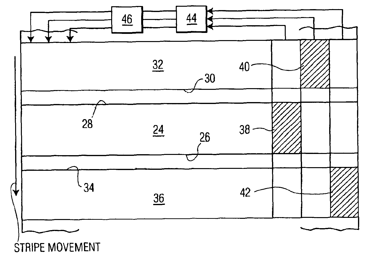
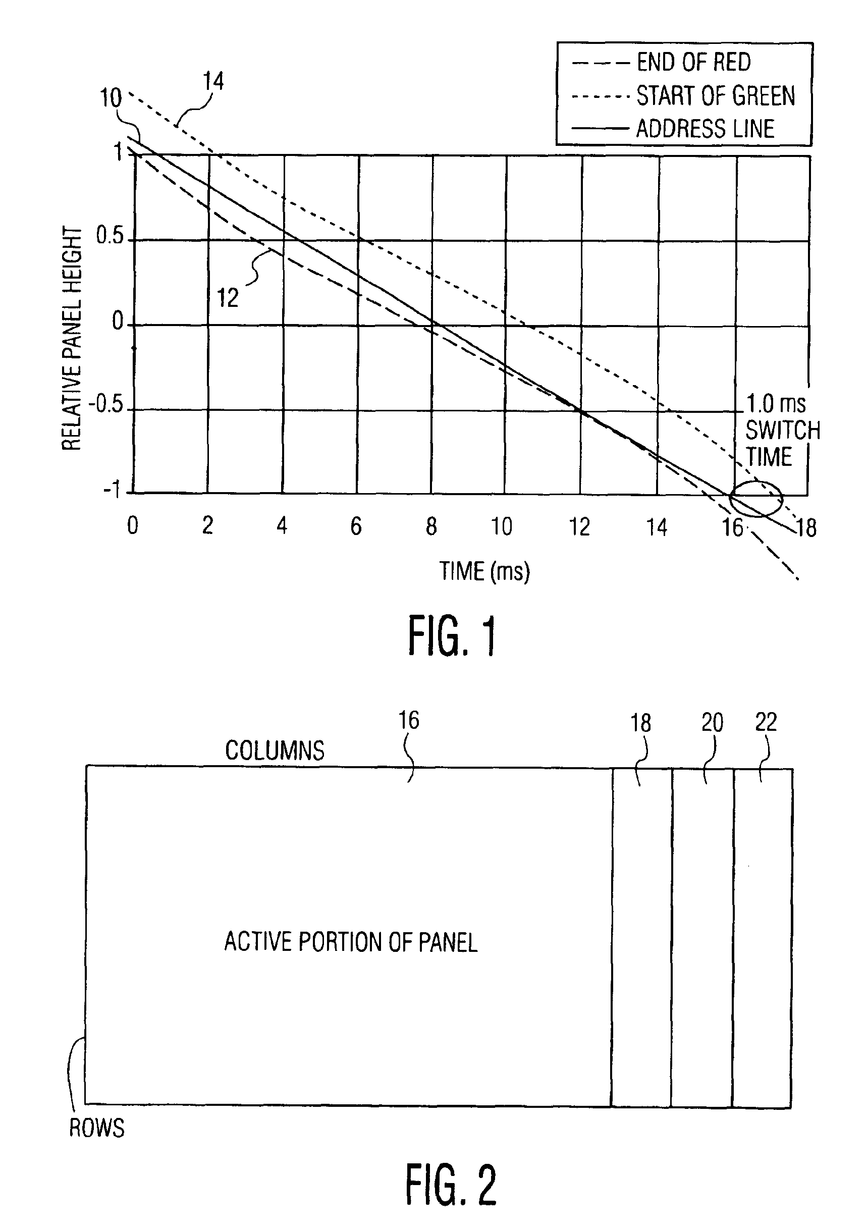
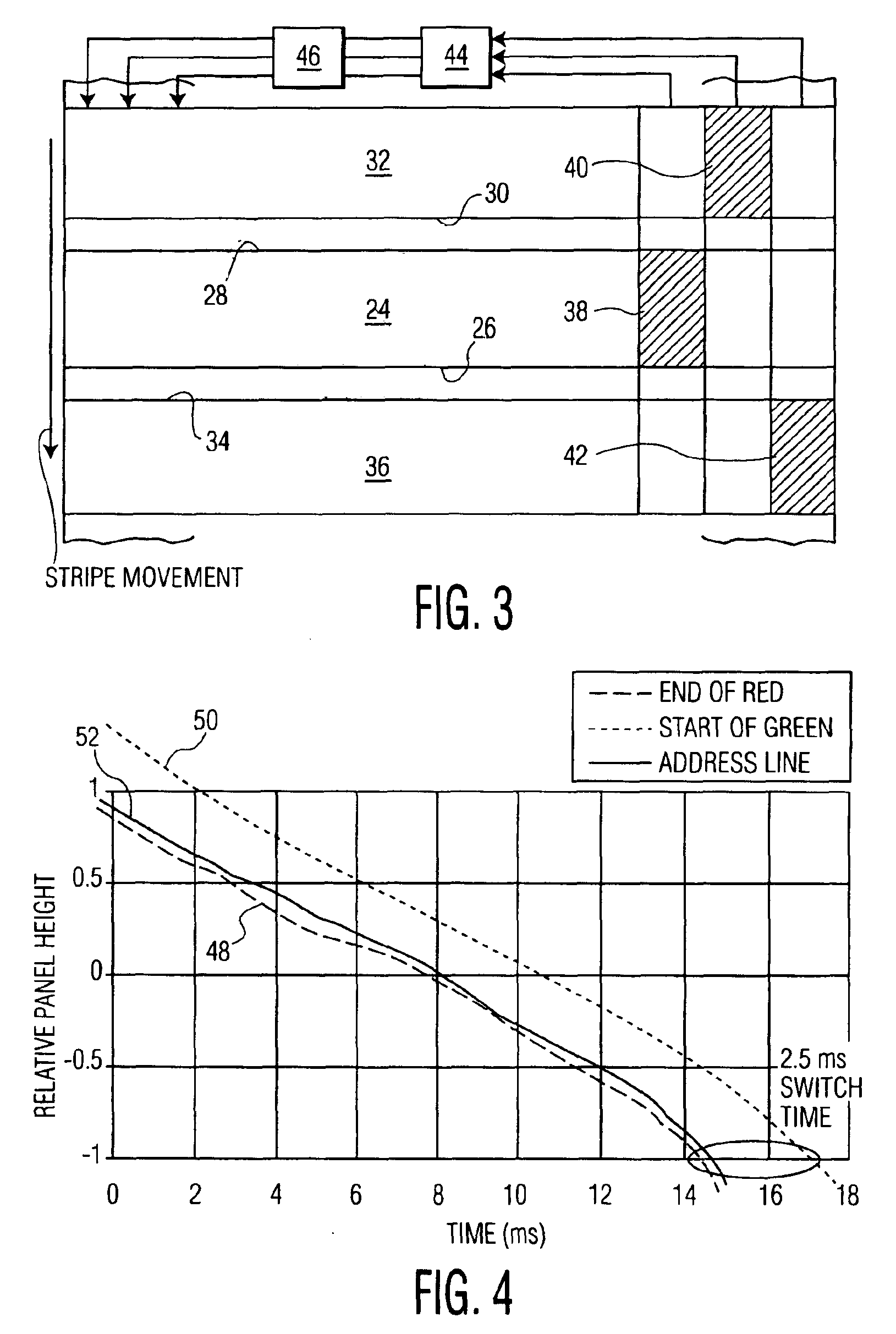
[0012]Optical scans of LCD panels with successive color stripes (red, green and blue) are generated by a set of three scanning prisms. Although the prisms rotate at an essentially constant angular velocity, the stripes produced on the surface of the panel do not necessarily move at a constant linear velocity. This means that the distances between stripes (from the trailing edge of one stripe to the leading edge of the next) may change as the stripes are scrolled across the surface of the panel as the relative velocity of the stripes varies. The electrical addressing of the rows of the panel with data relating to the next color to be scanned proceeds at a constant, linear velocity irrespective of the velocities of the color stripes. To effectively display an image on the panel, the electrical address must be applied to a row at least a certain minimum time prior to the color stripe impinging upon that row in order to allow sufficient time for the pixels on the panel to switch from on...


PUM

PropertyMeasurementUnit
critical switching timeaaaaaaaaaa
colorsaaaaaaaaaa

Abstract

The electrical scan which applies data for one of the red, green and blue colors of a liquid crystal display (LCD) to the pixels of each row of the display and the optical scan of the panel with the color stripe of that color are synchronized to ensure sufficient time for the switching of the pixel from one color value to another. Synchronizing the electrical and optical scans creates a better color rendition of the displayed image without any inter-color mixing artifacts. Arrays or groups of photosensors are positioned laterally adjacent the active portion of the panel and each array is covered by a filter which passes light of only one of the three colors (red, green and blue) used in the display. The color stripes providing the optical scan are scrolled simultaneously over both the active portion of the panel and the arrays of sensors, with the electrical signals from the sensors providing an indication of the positions of the leading and trailing edges of each color stripe at each instant, and thus the instantaneous velocity of each stripe. The signals from the sensors are provided to a control circuit which determines the order in which the rows of pixels are addressed and for which of the colors to provide data in each addressed location in order to maintain the critical switching time in spite of variations in relative velocities of the three color stripes.

Description

TECHNICAL FIELD[0001]The present invention relates generally to color liquid crystal displays (LCD) wherein red, green and blue color stripes are sequentially scanned over a panel made up of a multiplicity of pixels arranged in rows and, more particularly, to methods and apparatus for creating a better color rendition of the displayed image without any inter-color mixing artifacts by synchronizing the optical scan and the electrical addressing scan.BACKGROUND AND SUMMARY OF THE INVENTION[0002]Single-panel, color LCD systems are commonly driven by signals generated in response to an optical scan, produced by the successive scrolling of differently colored stripes, usually red, green and blue, over the pixels making up the panel, and an electrical scan, representing addresses of the rows of pixels with the signal corresponding to the color of the light impinging on the row. The optical scan is often generated by a set of three scanning prisms, although rotating color wheels and other ...

Claims


Application Information

Patent Timeline
Patent Type & Authority Patents(United States)
IPC IPC(8): G09G3/34H04N9/31G02F1/133G09G3/20G09G3/36H04N3/12H04N5/74
CPCG09G3/342H04N9/3197H04N9/3117G09G2310/0235G09G2310/024G09G2360/145G09G2310/08
Inventor DALAL, SANDEEP M.
Owner KONINKLIJKE PHILIPS ELECTRONICS NV
Why Eureka
Try Eureka