Transflective LCD device having color filters with through holes

a liquid crystal display and transparent technology, applied in bridge construction, instruments, construction, etc., can solve the problems of inability to use for an extended period of time, inability to meet the needs of users, and large battery consumption of reflective-type lcd devices, etc., to achieve uniform color purity, uniform color reproduction, and uniform color purity

Inactive Publication Date: 2006-05-30
LG DISPLAY CO LTD
View PDF7 Cites 20 Cited by
  • Summary
  • Abstract
  • Description
  • Claims
  • Application Information

AI Technical Summary

Benefits of technology

[0018]An advantage of the present invention is to provide a transflective liquid crystal display device to produce uniform color purity and uniform color reproduction.
[0019]Another advantage of the present invention is to provide a method of fabricating a transflective liquid crystal display device to produce uniform color purity and uniform color reproduction.
[0020]Another advantage of the present invention is to provide a transflective liquid crystal display device and a method of fabricating the same, which produce uniform and stable brightness.
[0021]Another advantage of the present invention is to provide a transflective liquid crystal display device and a method of fabricating the same having high transmittance and color purity.

Problems solved by technology

As a result, the transmissive-type LCD device requires a relatively high initial brightness, whereby the electrical power consumption required by the backlight device increases.
Accordingly, a relatively heavy battery, which cannot be used for an extended period of time, is needed to supply sufficient power to the backlight device.
However, the reflective-type LCD device is easily affected by its surroundings.
For example, because ambient light in an office differs largely from that outdoors, the reflective-type LCD device can not be used where the ambient light is weak or does not exist.
The transflective liquid crystal display device having the structure of FIG. 1 has a disadvantage due to the difference in the light efficiency between reflective mode and transmissive mode operation.
Thus, the aforementioned liquid crystal display device produces unstable brightness and color reproduction, which are different between the reflective mode and the transmissive mode.
However, these modifications also have some disadvantages.
Today when a transflective liquid crystal display device is utilized in mobile phones or PDAs, the image quality becomes an important issue in satisfying buyer's demands.
However, if the pixel size for the transflective liquid crystal display device is reduced, the reflective portion in the transflective liquid crystal display device is also reduced and a decrease in brightness results.

Method used


Image

  • Transflective LCD device having color filters with through holes
  • Transflective LCD device having color filters with through holes
  • Transflective LCD device having color filters with through holes

Examples


Embodiment Construction

[0035]Reference will now be made in detail to embodiments of the present invention, examples of which are illustrated in the accompanying drawings.

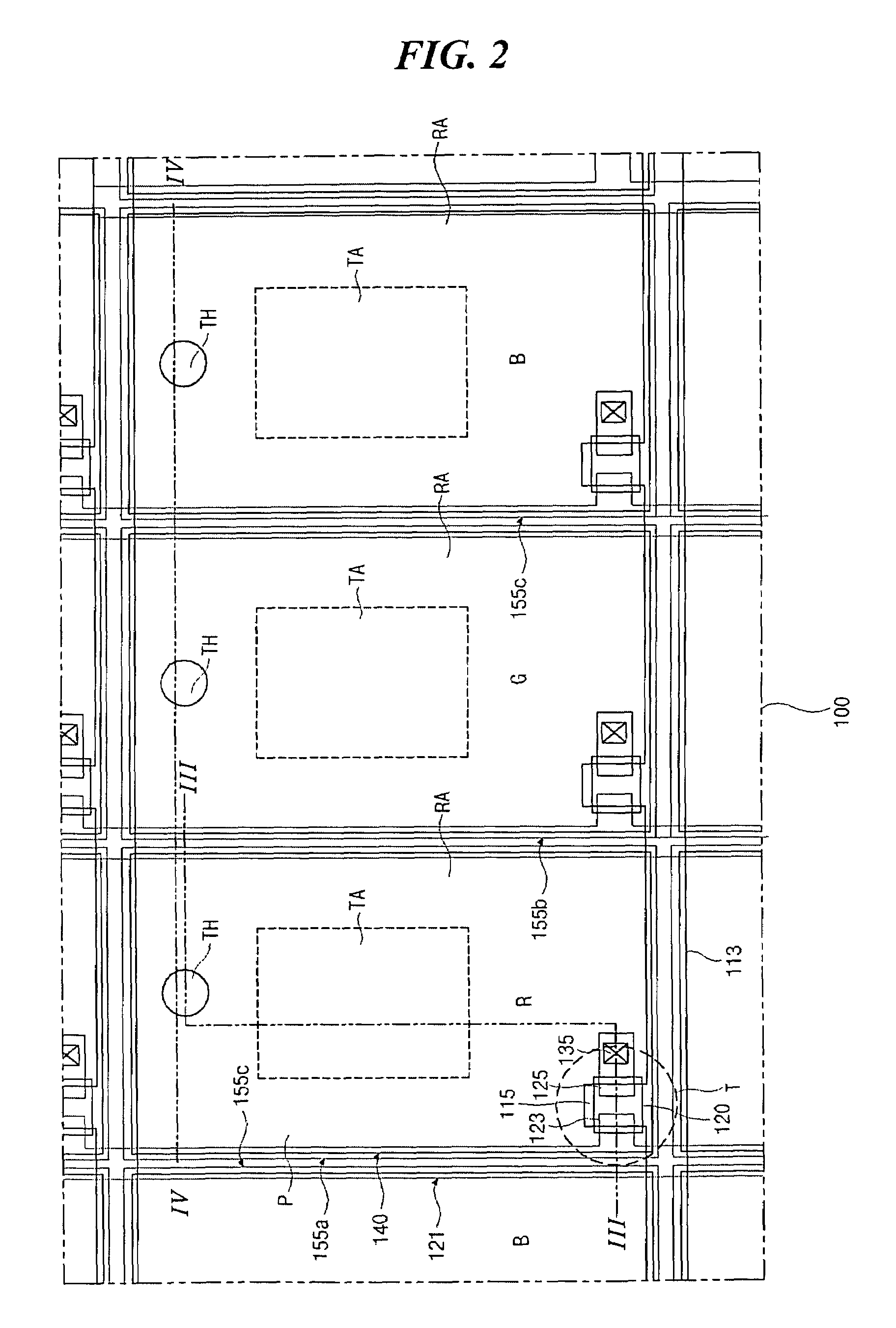
[0036]FIG. 2 is a plan view illustrating a transflective liquid crystal display device having a high resolution according to a first embodiment of the present invention.

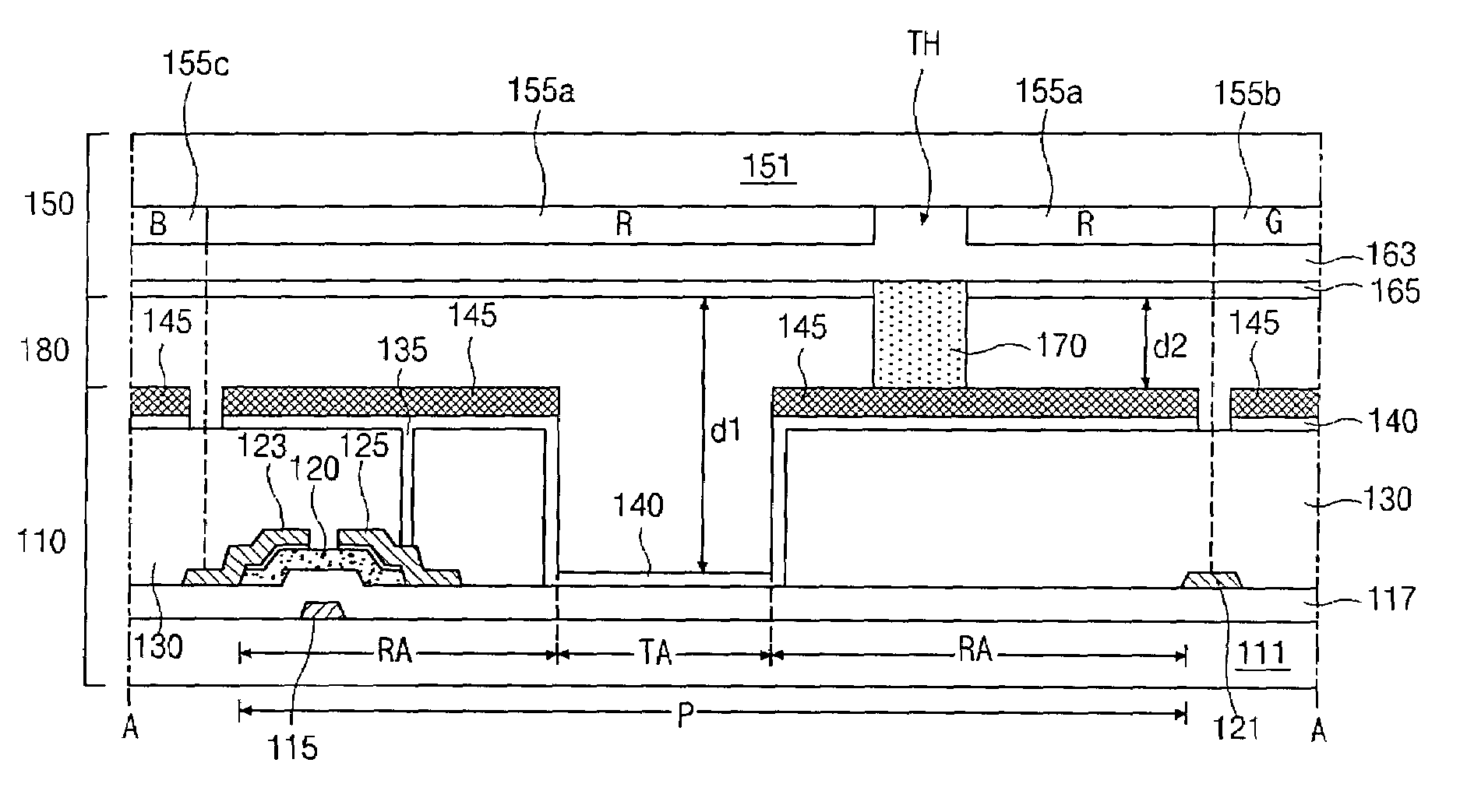
[0037]In FIG. 2, gate lines 113 are formed transversely on a first transparent substrate and a gate electrode 115 protrudes from the respective gate line 113. The gate lines and electrodes 113 and 115 may be formed of a metallic material. Data lines 121 cross the gate lines 113 and are substantially perpendicular to the gate lines 113. Also, a source electrode 123 extends from the source line 121 over one end portion of the gate electrode 115. Pairs of the gate and data lines 113 and 121 define pixel regions P. A drain electrode 135 is spaced apart from and faces the source electrode 123 across the gate electrode 115. The drain electrode 135 also overlaps the other end por...


PUM

PropertyMeasurementUnit
transmittanceaaaaaaaaaa
transparentaaaaaaaaaa
colorsaaaaaaaaaa

Abstract

A transflective liquid crystal display device including: first and second transparent substrates facing each other with a reflective portion and a transmissive portion; gate and data lines over the first transparent substrate perpendicularly crossing each other and defining pixel regions; a thin film transistor connected to the gate and data lines in the pixel region; an insulator in the thin film transistor on the first substrate covering the gate line; a passivation layer in the reflection portion on the insulator and on the thin film transistor; a pixel electrode in the reflective and transmissive portions, wherein the pixel electrode contacts both the passivation layer in the reflective potion and the insulator in the transmissive portion; a reflector on the pixel electrode in the reflective portion; color filters on a rear surface of the second transparent substrate, the color filters having through holes; column spacers formed between the reflector and the color filters, each column spacer corresponding in position to each through hole; a common electrode under the color filters; and a liquid crystal layer interposed between the common electrode and the pixel electrode.

Description

[0001]This application claims the benefit of Korean Patent Application No. 2003-0021390, filed in Korea on Apr. 4, 2003, which is hereby incorporated by reference for all purposes as if fully set forth herein.BACKGROUND OF THE INVENTION[0002]1. Field of the Invention[0003]The present invention relates to a liquid crystal display device and a method of fabricating a liquid crystal display device, and more particularly, to a transflective liquid crystal display device having through holes in color filters and a method of fabricating the same.[0004]2. Description of Related Art[0005]As the use of information technology increases, the need for flat panel displays with thin profiles, light weight, and lower power consumption has increased. Accordingly, various flat panel display (FPD) devices, such as liquid crystal display (LCD) devices, plasma display panel (PDP) devices, field emission display devices, and electroluminescence display (ELD) devices, have been developed.[0006]Presently,...

Claims


Application Information

Patent Timeline
Patent Type & Authority Patents(United States)
IPC IPC(8): G02F1/1339G02F1/1333G02F1/1335
CPCG02F1/133371G02F1/13394G02F1/133555G02F1/133514E01D22/00E01D21/00E02D27/04E01D2101/32
Inventor HWANG, HAN-WOOK
Owner LG DISPLAY CO LTD
Why Eureka
Try Eureka