Well perforating gun

a perforating gun and well technology, applied in the field of well perforating guns, can solve the problems of affecting the quality of the gun, the cost of materials, and the jamming of the casing,

Inactive Publication Date: 2006-06-06
KASH EDWARD CANNOY
View PDF13 Cites 19 Cited by
  • Summary
  • Abstract
  • Description
  • Claims
  • Application Information

AI Technical Summary

Problems solved by technology

A gun must allow explosions to penetrate the gun body, but not allow the tubing to split or otherwise lose its original shape Extreme distortion of the gun may cause it to jam within the casing.
Although effective, guns are relatively expensive.
Most of the expense involved in manufacturing guns is the cost of material.
Unfortunately, these efforts have seen only limited success.

Method used


Image

  • Well perforating gun
  • Well perforating gun
  • Well perforating gun

Examples


Embodiment Construction

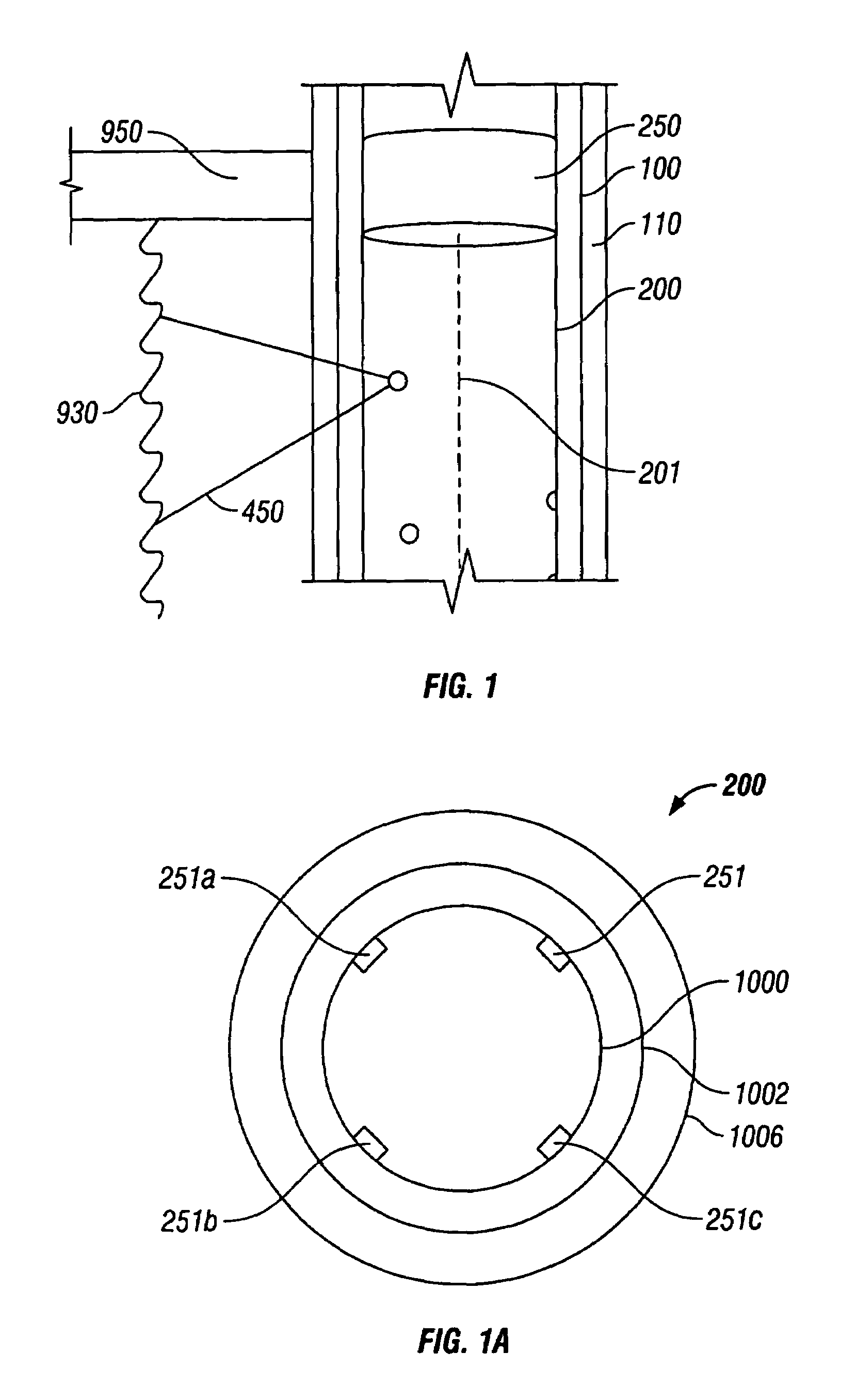
[0028]The invention disclosed herein provides for an improved well perforating gun.

[0029]According to the invention, the material, which can be steel or another metal, used in the gun has been improved to a set of desired characteristics.

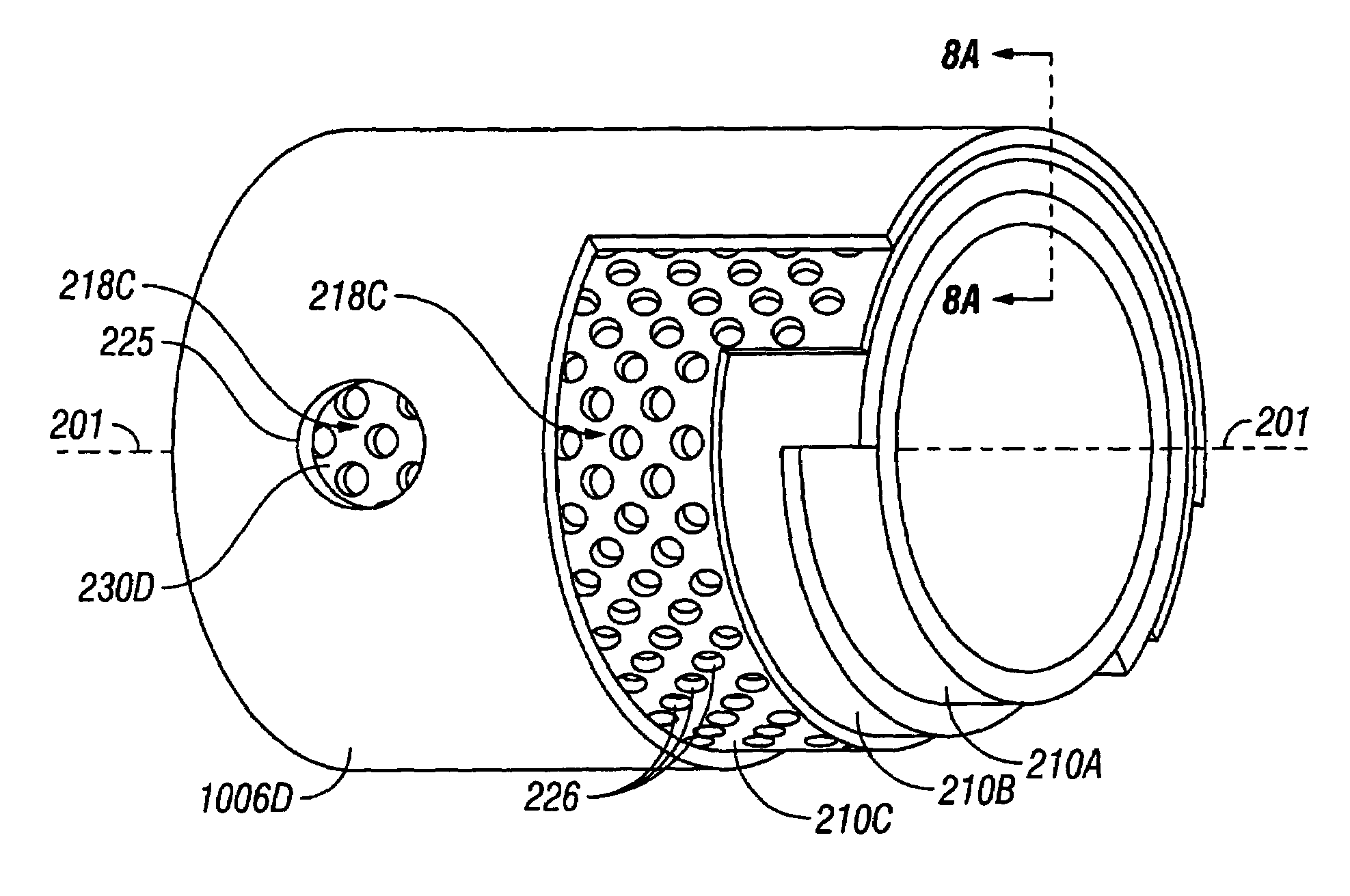
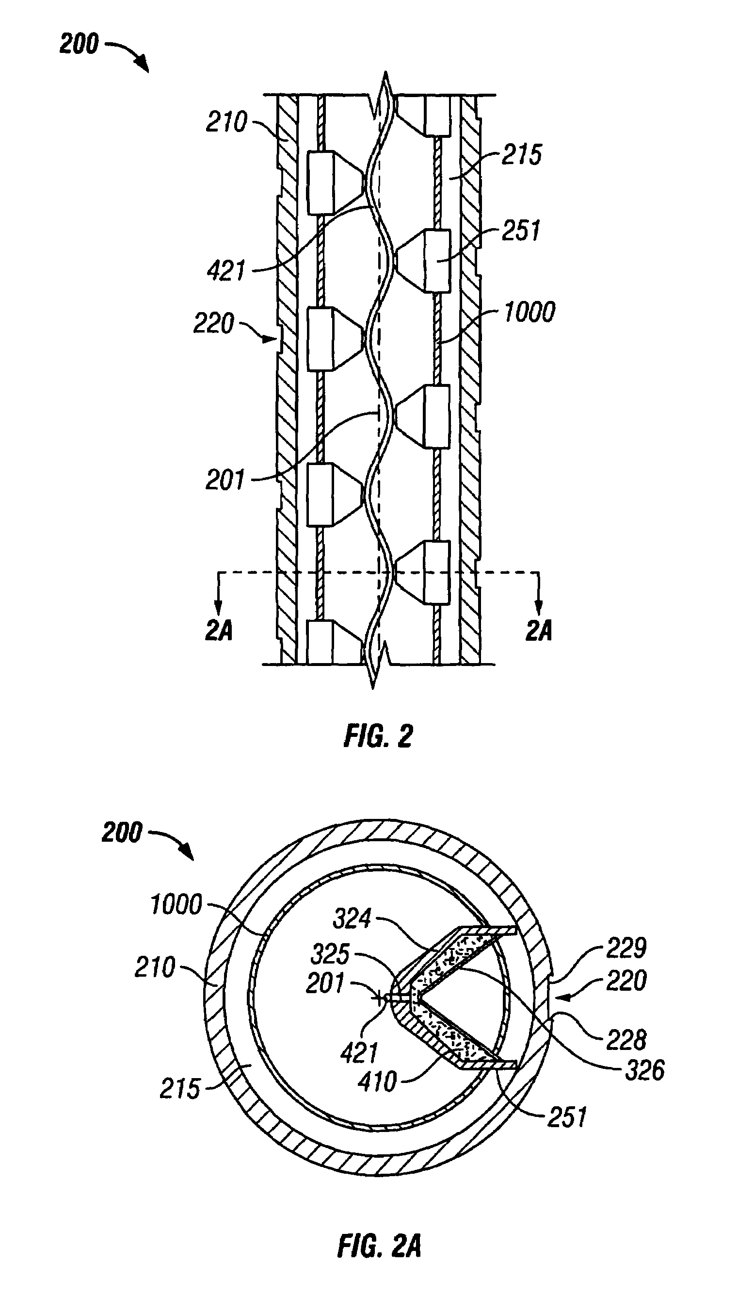
[0030]In one embodiment, the gun is design with an improved ability to withstand high shocks delivered over very short periods of time (“impact strength”) created by the simultaneous detonation of multiple explosive charges (“explosive energy pulse” or “pulse”). In essence, the impact strength normally associated with steels with 200 low carbon content and / or higher levels of other alloying elements, such as chromium and nickel is improved by using the design features of the invention.

[0031]In another embodiment, the overall strength of the gun is improved.

[0032]In a third embodiment, the ability of the gun to withstand the shock of the explosion from the gun by enabling the gun wall to transfer its energy immediately to the outside surface of the t...


PUM


Abstract

A perforating device having a longitudinal axis comprising: a loading tube having an explosive charge; a first layer slidable, non fixedly, and removeably disposed over the loading tube; and at least one outer layer in fixed engagement over the first layer and wherein the outer layer is a solid structure.

Description

[0001]This application is a continuation-in-part of application of Ser. No. 10 / 370,142 filed Feb. 18, 2003, now U.S. Pat. No. 6,865,978 Entitled, “WELL PERFORATING GUN”.BACKGROUND[0002]Well completion techniques normally require perforation of the ground formation surrounding the borehole to facilitate the flow if interstitial fluid (including gases) into the hole so that the fluid can be gathered. In boreholes constructed with a casing such as steel, the casing must also be perforated. Perforating the casing and underground structures can be accomplished using high explosive charges. The explosion must be conducted in a controlled manner to produce the desired perforation without destruction or collapse of the well bore.[0003]Hydrocarbon production wells are usually lined with steel casing. The cased well, often many thousands of feet in length, penetrates varying strata of underground geologic formations. Only a few of the strata may contain hydrocarbon fluids. Well completion tec...

Claims


Application Information

Patent Timeline
Patent Type & Authority Patents(United States)
IPC IPC(8): E21B43/116E21B43/117E21B43/119F42B1/02F42B12/76
CPCE21B43/117F42B12/76F42B1/02E21B43/119
Inventor KASH, EDWARD CANNOY
Owner KASH EDWARD CANNOY
Why Eureka
Try Eureka