Ignition timing control apparatus for internal combustion engine

a technology of ignition timing control and internal combustion engine, which is applied in the direction of electric control, ignition automatic control, machines/engines, etc., can solve the problems of uneven fuel distribution in the combustion chamber, improper ignition timing, and slow combustion rate of air-fuel mixtur

Inactive Publication Date: 2006-06-06
TOYOTA JIDOSHA KK
View PDF17 Cites 101 Cited by
  • Summary
  • Abstract
  • Description
  • Claims
  • Application Information

AI Technical Summary

Benefits of technology

[0010]In view of the aforementioned conventional problems, an object of the present invention is to provide an ignition timing control apparatus for an internal combustion engine that includes an in-cylinder injector and an intake-port injector, reducing the possibilities for example of occurrence of knocking due to excessive advance and insufficient output power due to excessive retard.

Problems solved by technology

A resultant problem is that, if ignition is simply caused for operation based on an ignition timing value that is set according to an operation state, the ignition timing is improper.
For example, when the fuel is injected from the in-cylinder injector, it is likely that the fuel distribution in the combustion chamber is uneven as compared with the case where the fuel is injected from the intake port injector.
If the air-fuel mixture is ignited in the state where the fuel distribution is uneven, combustion proceeds slowly in a low-fuel-concentration portion and thus the combustion rate of the air-fuel mixture tends to be slow.
Even if the fuel distribution is not uneven, latent heat of the injected fuel causes the temperature of the air-fuel mixture in the cylinder to decrease, resulting in a low combustion rate.
Otherwise, such abnormal combustion as knocking occurs or the output power is insufficient.
In such a state, if the ignition timing is set to the one determined in a stable state, knocking due to excessive advance or insufficient output power due to excessive retard for example could occur because of the ignition timing that is different from a proper value.

Method used


Image

  • Ignition timing control apparatus for internal combustion engine
  • Ignition timing control apparatus for internal combustion engine
  • Ignition timing control apparatus for internal combustion engine

Examples


Embodiment Construction

[0035]Embodiments of the present invention are hereinafter described with reference to the drawings.

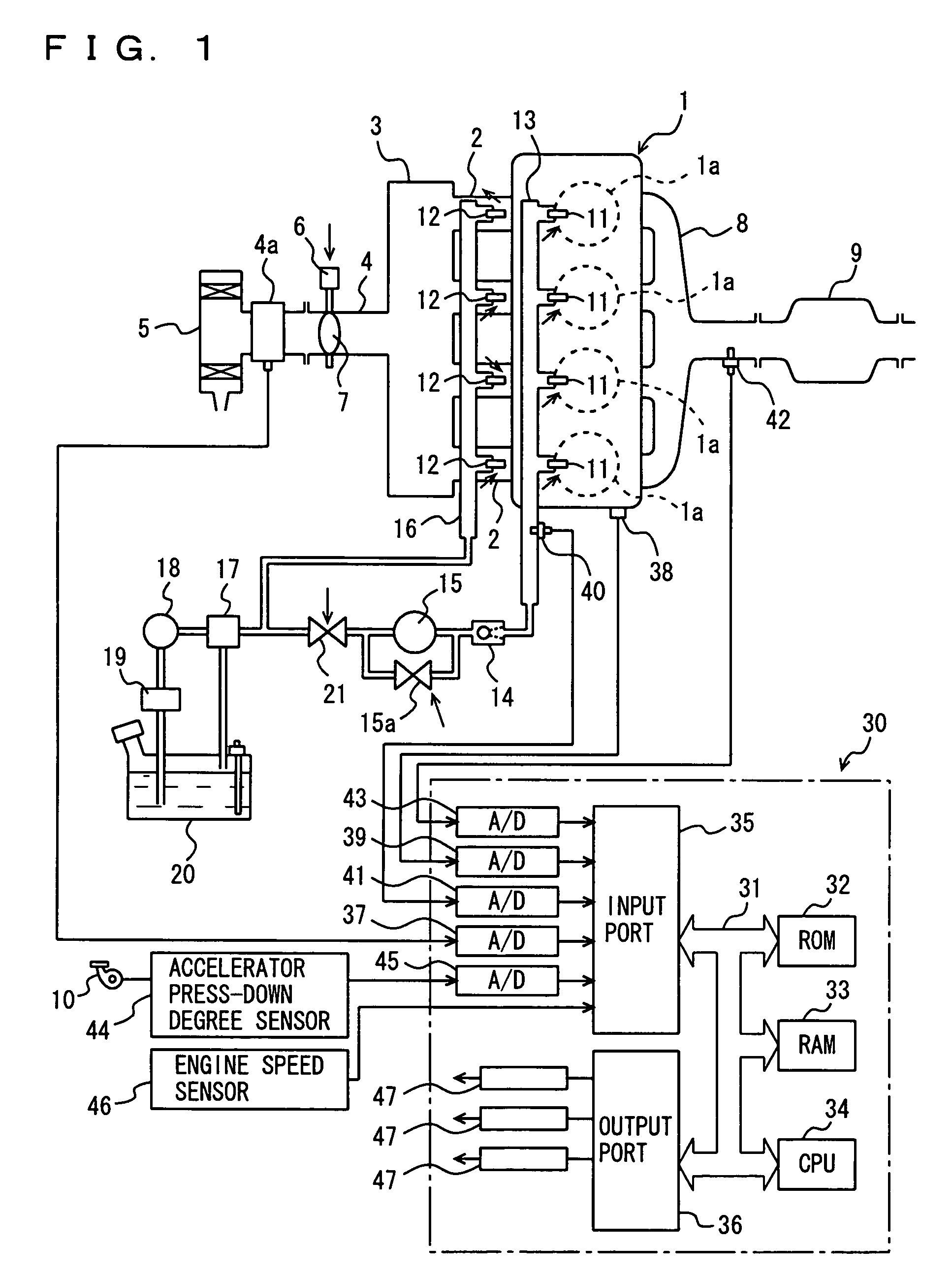
[0036]Referring to FIG. 1 that schematically shows a configuration of a dual-injection-type internal combustion engine to which an ignition timing control apparatus of the present invention is applied, an engine 1 includes four cylinders 1a. Cylinders 1a are connected through corresponding intake manifold branches 2 respectively to a common surge tank 3. Surge tank 3 is connected through an intake duct 4 to an airflow meter 4a and airflow meter 4a is connected to an air cleaner 5. Within intake duct 4, a throttle valve 7 driven by a step motor 6 is provided. This throttle valve 7 opens / closes intake duct 4 substantially in accordance with press-down of an accelerator pedal 10. Cylinders 1a are connected to a common exhaust manifold 8 and this exhaust manifold 8 is connected to a three-way catalytic converter 9.

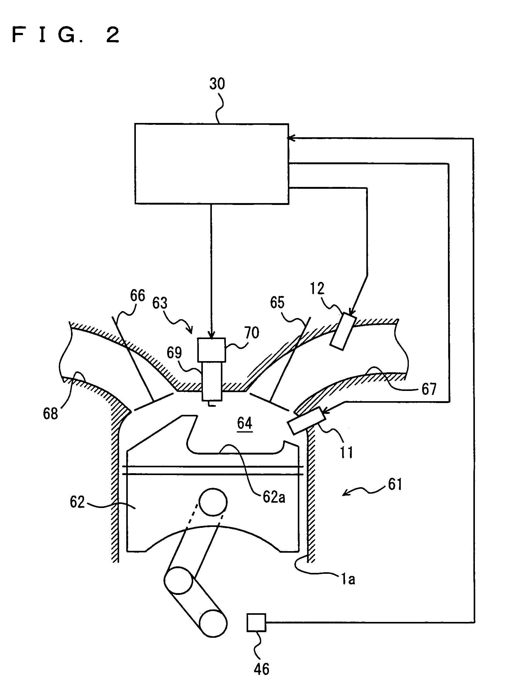
[0037]To each cylinder 1a, an in-cylinder injector 11 for injecting a fuel ...


PUM


Abstract

For an internal combustion engine including an in-cylinder injector and an intake port injector, proper ignition timing setting means is provided for setting a proper ignition timing according to the fuel injection ratio between injection from the in-cylinder injector and injection from the intake port injector. When a change is made in the fuel injection ratio, the proper ignition timing setting means selects one of a proper ignition timing value before the change and a proper ignition timing value after the change that is on the retard side and sets the ignition timing at the selected proper ignition timing value in at least a predetermined period of time after the change.

Description

[0001]This nonprovisional application is based on Japanese Patent Application No. 2004-224716 filed with the Japan Patent Office on Jul. 30, 2004, the entire contents of which are hereby incorporated by reference.BACKGROUND OF THE INVENTION[0002]1. Field of the Invention[0003]The present invention relates to an ignition timing control apparatus for an internal combustion engine, and particularly to an ignition timing control apparatus for an internal combustion engine of so-called dual injection type that includes an in-cylinder injector for injecting a fuel into a cylinder and an intake port injector for injecting a fuel into an intake manifold or intake port.[0004]2. Description of the Background Art[0005]An internal combustion engine of so-called dual injection type is known from Japanese Patent Laying-Open No. 2001-020837. This internal combustion engine includes an in-cylinder injector for injecting a fuel into a cylinder and an intake port injector for injecting a fuel into an...

Claims


Application Information

Patent Timeline
Patent Type & Authority Patents(United States)
IPC IPC(8): F02P5/15F02D41/24F02D41/30
CPCF02P5/1502F02D41/3094F02D41/2422F02D41/3029Y02T10/46F02P5/1504Y02T10/40
Inventor MIYASHITA, SHIGEKITANAKA, HIROSHIHOKUTO, HIROYUKI
Owner TOYOTA JIDOSHA KK
Why Eureka
Try Eureka