Bicycle rack

a bicycle rack and bicycle technology, applied in the field of bicycle racks, can solve the problems of damage to bicycles, heavy structure, and lack of kick stands for reducing weight and increasing performance, and achieve the effects of quick and easy sliding, quick and easy disassembly and storage, and easy lifting

Inactive Publication Date: 2006-06-06
COLONY
View PDF26 Cites 17 Cited by
  • Summary
  • Abstract
  • Description
  • Claims
  • Application Information

AI Technical Summary

Benefits of technology

[0011]The present invention affords several advantages. Initially, the sleeve allows a rack or a plurality of racks to be quickly and easily slid onto an elongate 2 by 4 for holding one or a plurality of differently sized bicycles in spaced-apart relationship. The sleeve structure allows the rack to be used at public parks, schools or other venues such as bicycle races where several bicycles must be held in place. The sleeve structure allows such a multiple stand-alone rack embodiment to be quickly and easily disassembled and stored away. Moreover, the sleeve structure allows racks to be mounted on opposite sides of the 2 by 4 for holding bicycles on both sides of the 2 by 4.
[0012]Another advantage of the ra

Problems solved by technology

However, bicycles such as racing bicycles and mountain bicycles are not equipped with kick stands to reduce weight and increase performance.
These parking methods often result in damage to the bicycle as when, for example, a bicycle slides and falls away from the wall agains

Method used


Image

  • Bicycle rack
  • Bicycle rack
  • Bicycle rack

Examples


Embodiment Construction

[0022]The invention disclosed herein is, of course, susceptible of embodiment in may different forms. Shown in the drawings and described hereinbelow in detail are preferred embodiments of the invention. It is to be understood, however, that the present disclosure is an exemplification of the principles of the invention and does not limit the invention to the illustrated embodiments.

[0023]For ease of description, a bicycle rack embodying the present invention is described as shown in the accompanying drawings where the rack is fitted on a support member which is seated on a generally horizontal support surface and terms such as upper, lower, horizontal, vertical, etc., will be used herein with reference to this position as shown in the drawings.

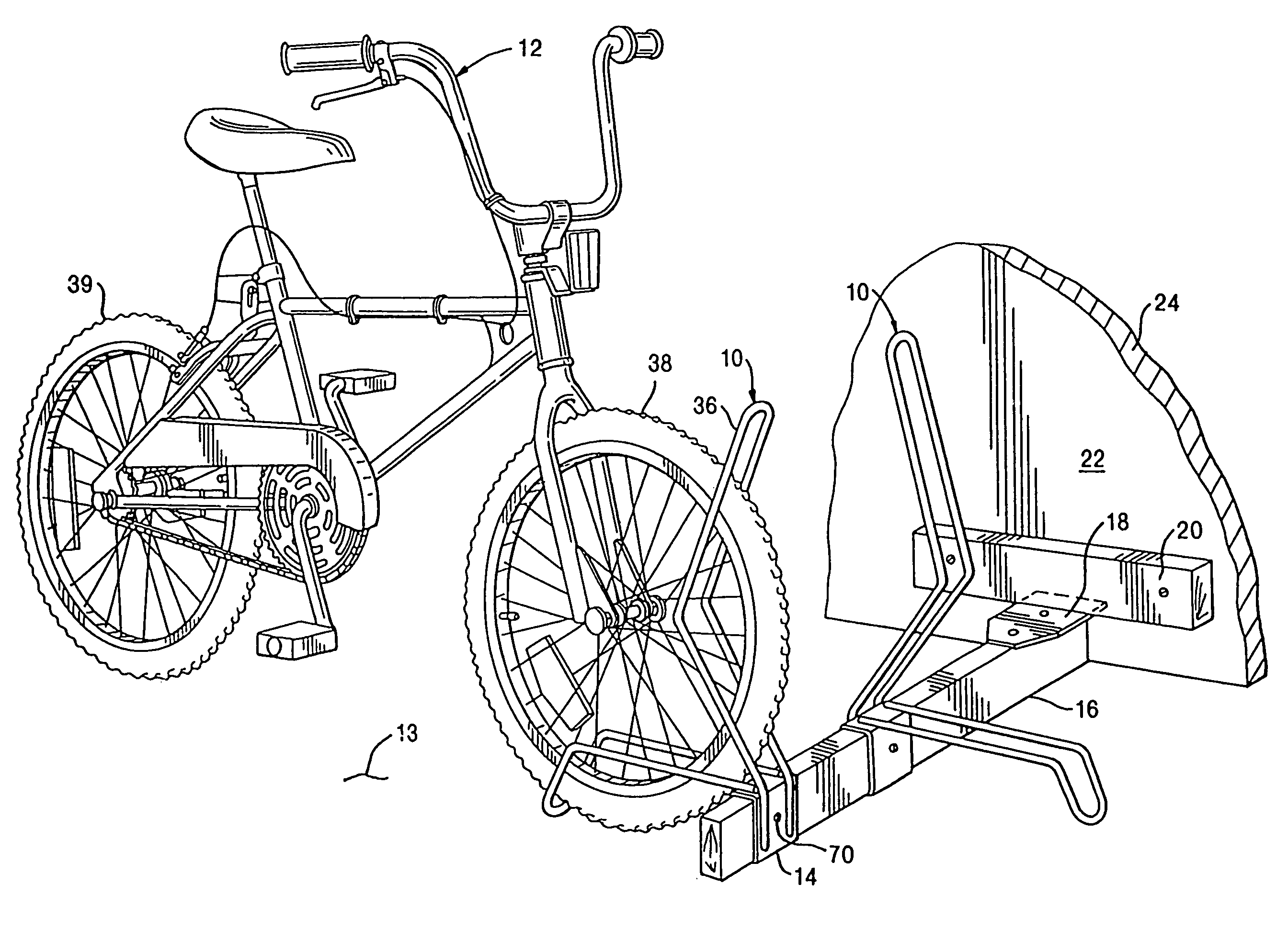
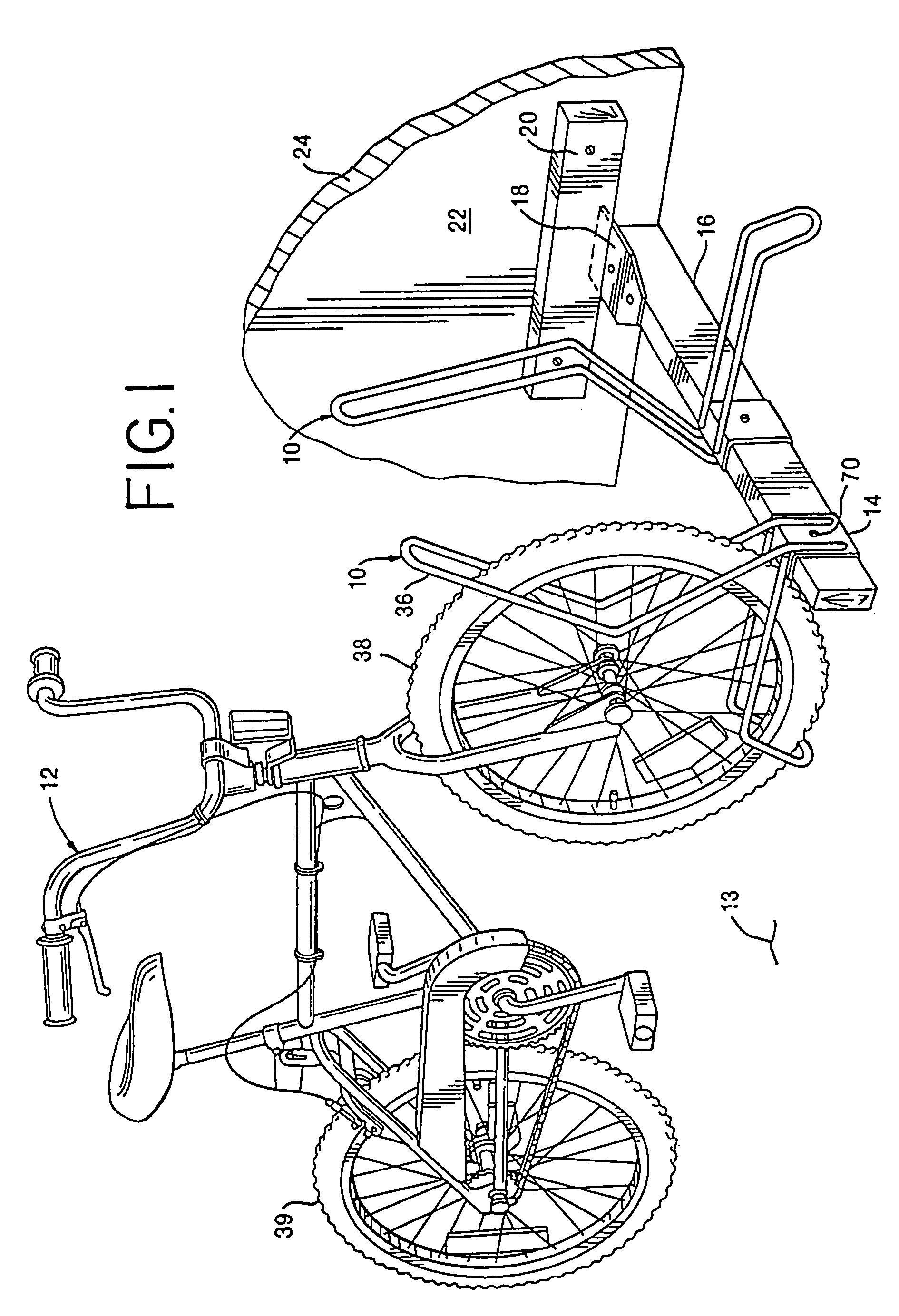
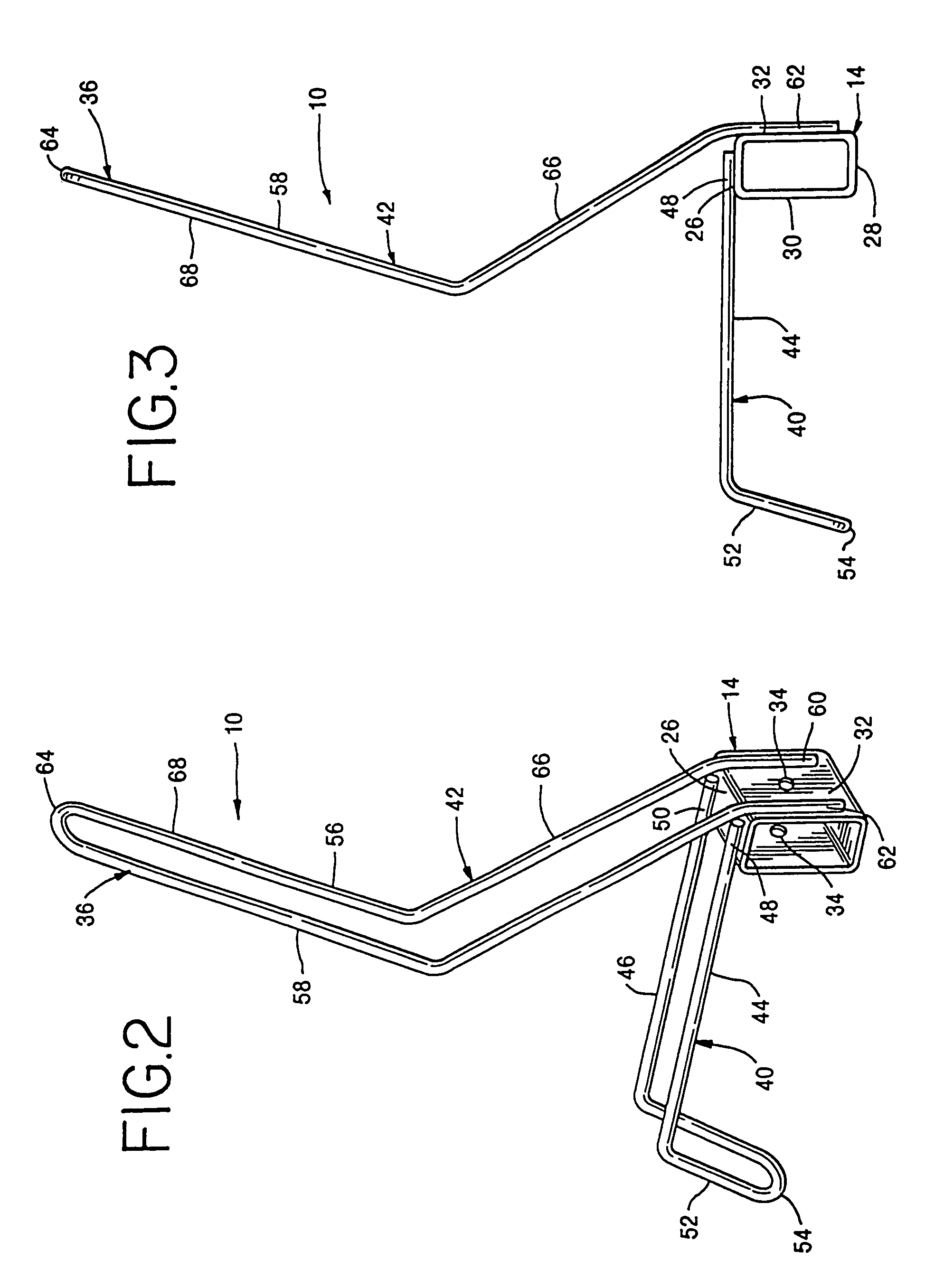
[0024]Referring now to the drawings and more particularly, to FIGS. 1–3, there is shown therein a bicycle rack 10 constructed in accordance with the present invention for holding a bicycle 12 in an upright, parked position relative to a bicyc...


PUM


Abstract

A rack for holding a bicycle by either its front or back wheel in an upright position on a floor. The rack includes a bracket which is adapted to be fitted on an elongate support frame. A rotatable lower brace extends outwardly from the bracket and includes spaced-apart arms which terminate in a downwardly extending lip. An upper brace extends generally upwardly from the bracket and includes spaced-apart arms. A bicycle is held on the rack by rolling the bicycle wheel directly into the lip of the lower brace and into and between the arms of the upper and lower braces respectively. A plurality of racks can be slidingly fitted onto a single support frame for holding a plurality of bicycles in spaced-apart relationship.

Description

CROSS REFERENCE TO RELATED APPLICATION[0001]This application is a division of U.S. application Ser. No. 09 / 450,961 filed on Nov. 30, 1999, now U.S. Pat. No. 6,588,603, which, in turn, is a continuation-in-part of U.S. application Ser. No. 08 / 905,302 filed on Aug. 1, 1997, now U.S. Pat. No. 5,992,645.FIELD OF THE INVENTION[0002]This invention relates to a bicycle rack and, more particularly, to a rack for holding a bicycle by its front or back wheel in an upright position on a support surface.BACKGROUND OF THE INVENTION[0003]Many types of racks and stands have been used for holding bicycles in a parked upright position. A commonly used stand for holding a bicycle in its normal upright position is the “kick stand”, i.e., a bar swingably mounted to the frame of a bicycle. However, bicycles such as racing bicycles and mountain bicycles are not equipped with kick stands to reduce weight and increase performance. These bicycles are typically “parked” by either laying them flat on their si...

Claims


Application Information

Patent Timeline
IPC IPC(8): A47F7/00B62H3/04
CPCB62H3/04
Inventor WEST, KENT G.
Owner COLONY
Why Eureka
Try Eureka