Drive unit for vehicle

a technology for driving units and vehicles, applied in the direction of machines/engines, engine starters, engine rings, etc., can solve the problem that the oil pressure generated by the frictional engagement means cannot be generated before the engine, and achieve the effect of effective restraint, high speed and reduced load on the battery for supplying electric power

Active Publication Date: 2006-06-06
AISIN AW CO LTD +1
View PDF26 Cites 41 Cited by
  • Summary
  • Abstract
  • Description
  • Claims
  • Application Information

AI Technical Summary

Benefits of technology

[0011]Therefore, an object of the invention is to provide a drive unit for a vehicle able to reliably supply the oil pressure required in the engaging operation of the frictional engaging means of the stepped speed change gear even before the engine driving although the drive unit is a drive unit for the vehicle of the 2-motor split type having the stepped speed change gear, and structured so as to reliably prevent the uncomfortable feeling caused by the reaction force at the engine starting time so that the discussed problems are solved.
[0013]In accordance with the invention, the pump operation control means, operated on the basis of the engine starting signal outputted by turning on an ignition switch, etc., operates the electrically operated oil pump prior to the control of the engine driving control means based on the engine driving signal generated after the output of the starting signal. Accordingly, the electrically operated oil pump is operated before the second motor is driven prior to the engine starting. The operating oil pressure of the frictional engaging means can be reliably generated. Thus, although the drive unit has the stepped speed change gear of a structure unable to connect the second motor and the output section unless the frictional engaging means is engaged, the engine starting can be executed while a state able to restrain the reaction force in the power distributing means due to driving of the first motor is reliably attained. Accordingly, it is possible to reliably prevent an uncomfortable feeling caused by the reaction force at the engine starting time. The torque change caused by generating the driving force in starting the engine associatively rotated by driving the first motor can be absorbed by controlling the output torque of the second motor so as to cancel its torque increasing amount at the detecting time of this torque change e.g., while the torque applied to the output section is monitored by a sensor.
[0015]Further, in the drive unit for a vehicle, the stepped speed change gear is structured so as to be able to be switched to a plurality of speed change stages, and is switched to a low speed stage among the plurality of stages at the control time of the engine driving control means. Because the stepped speed change gear is switched to the low speed stage at the control time of the engine driving control means, the driving force of the second motor can be reduced. Further, the stepped speed change gear is switched to a high speed stage among the plurality of stages at the control time of the engine driving control means and can be also more effectively applied as driving force for restraining the reaction force due to the first motor.
[0017]Further, as the hydraulic controller has a first solenoid valve for high speed stage switching and a second solenoid valve for low speed stage switching, and the stepped speed change gear is switched to the low speed stage by engaging the brake on the low speed stage side on the basis of the operation of the second solenoid valve at the control time of the engine driving control means, the drive unit permits, at the engine starting time, the stepped speed change gear to be rapidly switched to the low speed stage on the basis of the operation of the second solenoid valve, and the state able to more effectively restrain the reaction force at the engine starting time can be reliably attained. Additionally, when the stepped speed change gear is switched to the high speed stage by engaging the brake on the high speed stage side on the basis of the operation of the first solenoid valve at the control time of the engine driving control means, the driving force of the second motor can be effectively applied as a driving force for restraining the reaction force due to the first motor. Thus, when the drive unit is structured such that the second solenoid valve is set to a non-operating state by turning off a power source and the first solenoid valve is set to an operating state by turning off the power source, the stepped speed change gear is rapidly switched to the high speed stage and the state for restraining the reaction force at the engine starting time can be reliably attained. Further, because the high speed is achieved by turning off the power source of both of the solenoid valves, the load applied to a battery for supplying electric power can be reduced.
[0018]A variation in the drive unit for a vehicle includes motor driving control means for controlling the operation of the second motor, the second motor is arranged within a case for storing oil to be supplied to the hydraulic controller, and the motor driving control means drives the second motor until a predetermined condition is satisfied prior to the operation starting of the electrically operated oil pump using the pump operation control means. Accordingly, because it is disadvantageous to operate the electrically operated oil pump when the oil temperature low and viscosity high before the engine is started, the pump can be operated in a state in which the oil within the case is agitated by driving the second motor and the oil temperature is raised and the viscosity is reduced by its agitating resistance. Thus, because the load of the electrically operated oil pump at its operation starting time is greatly reduced, the electrically operated oil pump can be reduced in size yet provide a preferable pump operation starting state and the mounting of the electrically operated oil pump to the vehicle can be improved.
[0019]Further, because the frictional engaging means can be operated by the oil pressure provided through the operation of the mechanical type oil pump when the engine is driven, the electrically operated oil pump can function as an auxiliary structure to the mechanical type oil pump. Accordingly, the electrically operated oil pump can be compact and the mounting to the vehicle can be further improved.

Problems solved by technology

However, for example, when a structure for interposing a stepped speed change gear between the second motor and the output shaft is considered and the control technique as mentioned above is intended to be applied to this structure, there is a fear that the following problems are caused.
However, in this case, even when the output torque of the second motor is intended to act as a torque for restraining the reaction force based on the first motor at the engine starting time, no oil pressure for the engagement of the frictional engaging means can be generated before the engine is started in that a mechanical type oil pump is normally provided.

Method used


Image

  • Drive unit for vehicle
  • Drive unit for vehicle
  • Drive unit for vehicle

Examples


Embodiment Construction

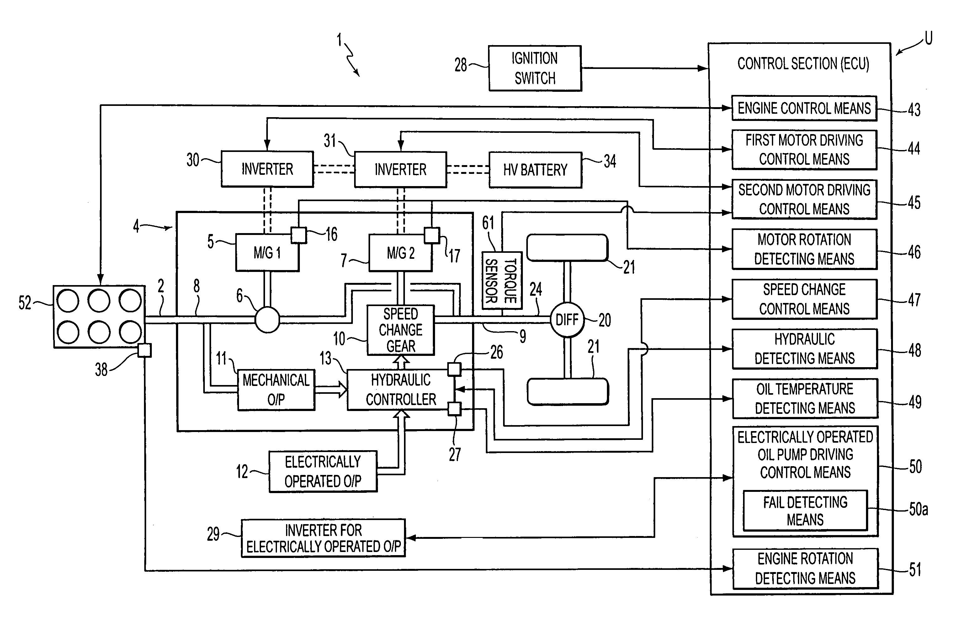
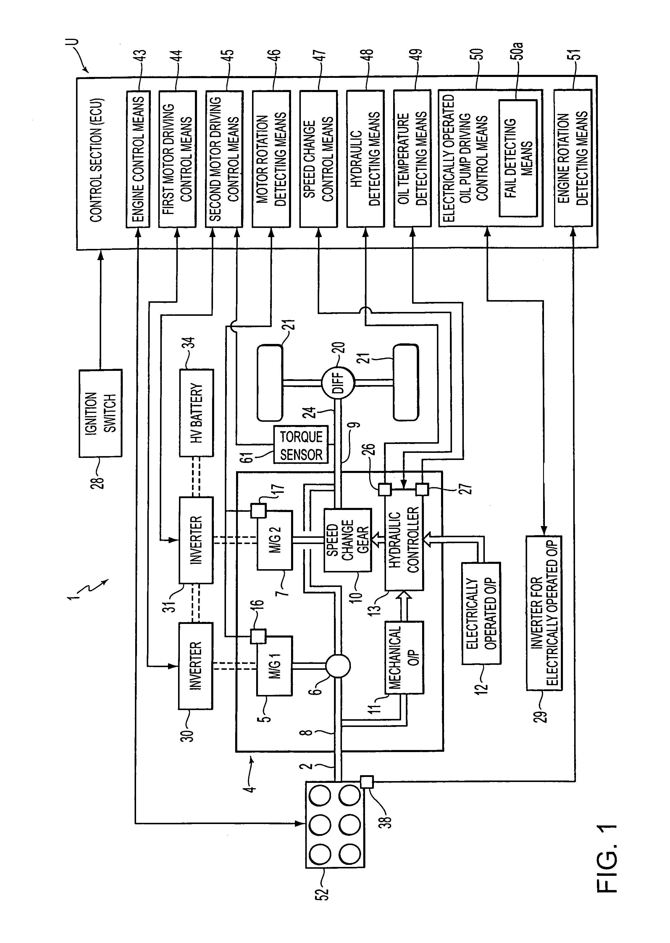
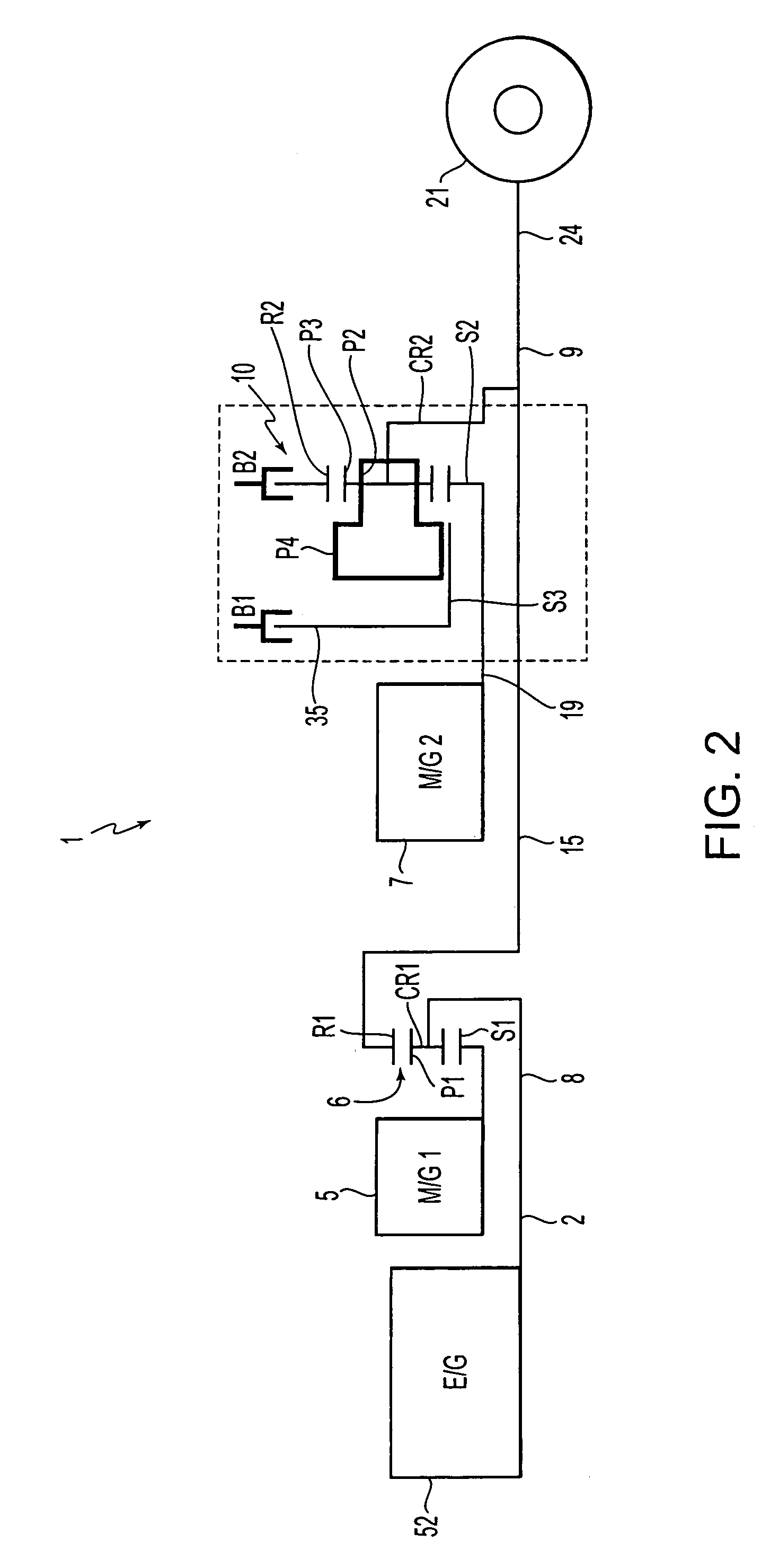
[0032]A first mode of the invention will now be explained. The structure of the drive unit for a vehicle in this mode will first be explained using FIG. 3. As shown, the drive unit 1 for a vehicle is structured as the 2-motor split type. The drive unit 1 has a damper device 3, a first motor 5, a power distributing planetary gear (power distributing means) 6, a second motor 7, and a stepped speed change gear 10 within a case 4. The damper device 3 is sequentially arranged in a uniaxial shape aligned with a crankshaft 2 from the side of an internal combustion engine 52 (FIGS. 1 and 2). The stepped speed change gear 10 has brakes B1, B2 able to change the rotating speed of the second motor 7 and transmit the rotation of the second motor 7 to an output shaft 9.

[0033]An input shaft 8 is arranged in the inner circumferential portion of the first motor 5 and the power distributing planetary gear 6 and is aligned with the crankshaft 2 in a uniaxial shape. Further, an intermediate shaft 15 i...


PUM


Abstract

The drive unit for a vehicle has an engine driving control element for driving a first motor on the basis of an engine driving signal, and driving a second motor so as to restrain a reaction force in a power distributing planetary gear due to the driving of the first motor in a state in which the stepped speed change gear connects the second motor and an output shaft by brakes. Further, the drive unit has an electrically operated oil pump for generating an operating oil pressure of the brakes, and also has a control section having an electrically operated oil pump operation control element for operating the electrically operated oil pump prior to the control of the engine driving control element on the basis of an engine starting signal outputted in a vehicle stopped state.

Description

[0001]This application claims priority from JP 2003-153120, filed May 29, 2003, the disclosure of which is incorporated herein in its entirety by reference thereto.BACKGROUND OF THE INVENTION[0002]1. Field of Invention[0003]The invention relates to a drive unit for a vehicle, and is applicable to a hybrid vehicle, etc., and more particularly relates to a drive unit for a vehicle which is of a type (a so-called 2-motor split type) having first and second motors (conceptually including a generator) and has a structure able to effectively restrain reaction force during engine starting on the basis of the driving of the first motor.[0004]2. Description of Related Art[0005]The so-called 2-motor split type structure is conventionally mounted to a vehicle, for example, the automobile identified as a PRIUS®, and is practically used as a hybrid drive unit. In this type, an output from an internal combustion engine (hereinafter also simply called the engine) is distributed to the first motor ...

Claims


Application Information

Patent Timeline
Patent Type & Authority Patents(United States)
IPC IPC(8): B60K6/00F02N11/04B60K6/365B60K6/445B60K6/547B60L50/16B60W10/00B60W10/02B60W10/04B60W10/06B60W10/08B60W10/10B60W10/11B60W10/115B60W10/30B60W20/00F16H59/74F16H61/00F16H61/02F16H61/68F16H61/684F16H61/686F16H63/40F16H63/50
CPCB60K6/365B60K6/48B60K6/547B60W10/02B60W10/06B60W10/08F16H61/0025F16H61/0031B60W20/00Y10T477/23F16H61/0204F16H2312/14Y02T10/6221Y02T10/6286Y02T10/62B60W30/18054B60K6/445B60W20/30B60W20/10
Inventor NAKAMORI, YUKINORIMIURA, KIYOTOMOWAKUTA, SATORUMOTOIKE, KAZUTOSHIADACHI, MASATOSHI
Owner AISIN AW CO LTD
Why Eureka
Try Eureka