Pressure and temperature sensors and methods of removing ice from pressure and temperature sensors

a technology of pressure and temperature sensors and sensors, applied in the field of pressure and temperature measurement, can solve the problems of sensor heating and sensor heating, and introduce de-icing heater errors into sensor measurements, and achieve the effect of limiting (or eliminating entirely) interference and reliable measurement of pressure and temperatur

Pending Publication Date: 2021-09-02
ROSEMOUNT AEROSPACE
View PDF0 Cites 4 Cited by
  • Summary
  • Abstract
  • Description
  • Claims
  • Application Information

AI Technical Summary

Benefits of technology

[0005]A sensor is provided. The sensor includes a mount arranged along a sensor axis, an airfoil body fixed to the mount and having a first face and second face extending axially along the sensor axis face, and a heater element. The heater element is positioned within the airfoil body and extends axially through the airfoil body. The airfoil body defines therein a pressure channel having an inlet segment extending between the heater element and the first face of the airfoil body to prevent ice formation and / or melt ice entrained within air traversing the pressure channel.
[0022]A method of making a sensor is also provided. The method includes forming an airfoil body having a first face and a second face extending along a sensor axis, defining a heater element seat and a pressure channel having an inlet segment extending between the heater element and the first face of the airfoil body to prevent ice formation and / or melt ice entrained within air traversing the pressure channel, defining an expansion chamber fluidly coupled to the inlet segment, and defining a temperature probe seat extending axially within the airfoil body using the additive manufacturing technique. A heater element is positioned within the airfoil body in the heater element seat such that the heater element extends axially through the airfoil body, a temperature probe positioned within the airfoil body in the temperature probe seat such the temperature probe extends axially through the airfoil body, and the airfoil body is fixed to a mount arranged along the sensor.
[0023]Technical effects of the present disclosure include the capability to reliably measure pressure and temperature in environments where the pressure and temperature sensor is exposed to entrained ice and ice accretion. In certain examples sensors described herein are provided with heating elements to limit (or eliminate entirely) ice accretion on the airfoil body. In accordance with certain examples sensors described herein include the capability to separate, impound, and melt ice entrained within ambient air entering the sensor. It is also contemplated that, in accordance with certain examples, sensors described herein include the capability to limit (or eliminate entirely) interference between heat generated by the heater element and the temperature measurements provided by the sensor. Further examples of sensor described herein include the capability to preferentially accrete ice at locations where the ice can periodically be shed without interfering with pressure and temperature sensing by the sensor.

Problems solved by technology

The ice and / or super-cooled moisture in such environments can interrupt operation of some sensor, such as when ingested within the sensor.
And while sensor heating can be employed as a countermeasure to ice and / or super-cooled moisture is present in the engine operating environment, sensor heating can introduce de-icing heater error into sensor measurements.

Method used


Image

  • Pressure and temperature sensors and methods of removing ice from pressure and temperature sensors
  • Pressure and temperature sensors and methods of removing ice from pressure and temperature sensors
  • Pressure and temperature sensors and methods of removing ice from pressure and temperature sensors

Examples


Embodiment Construction

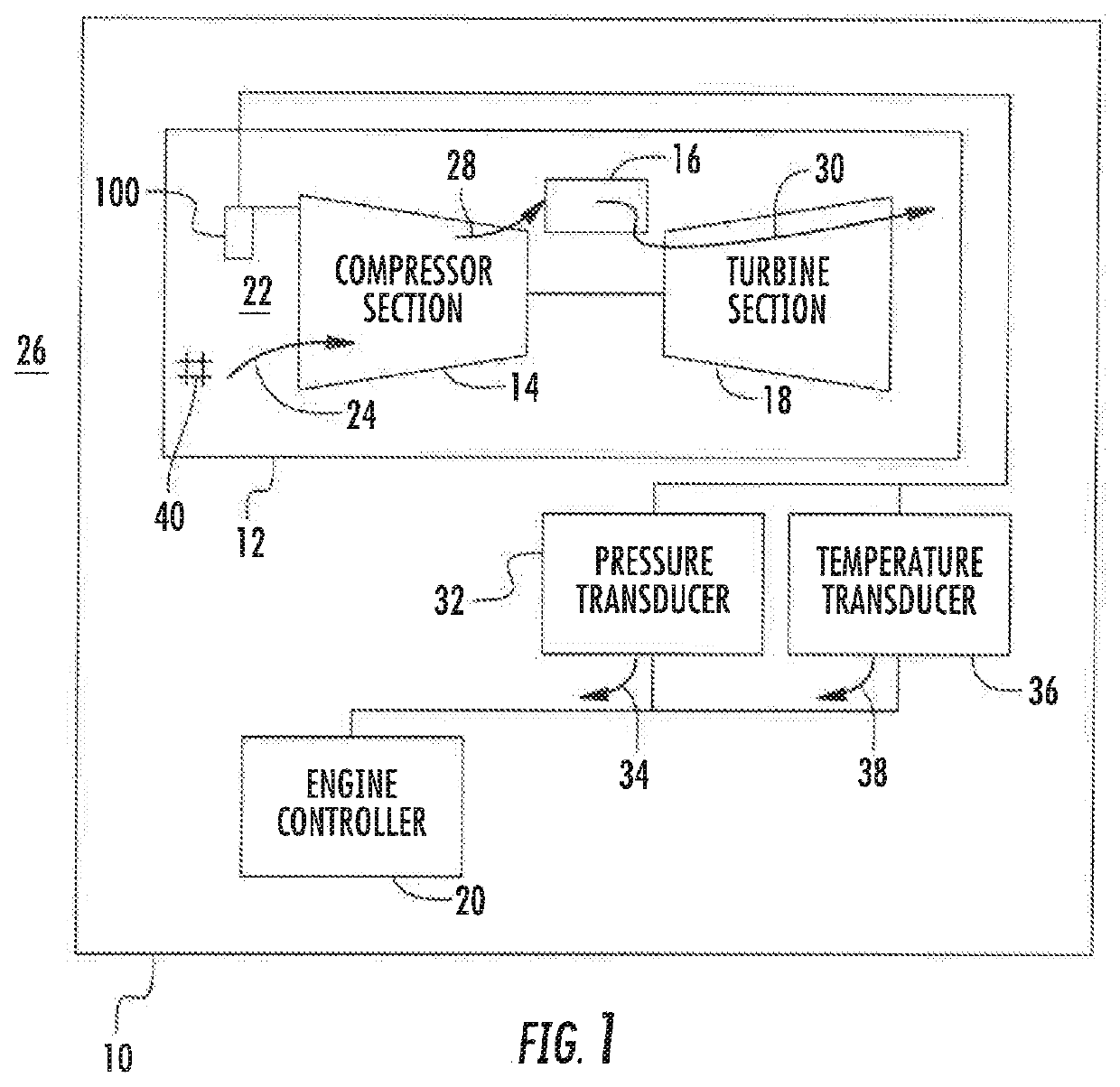
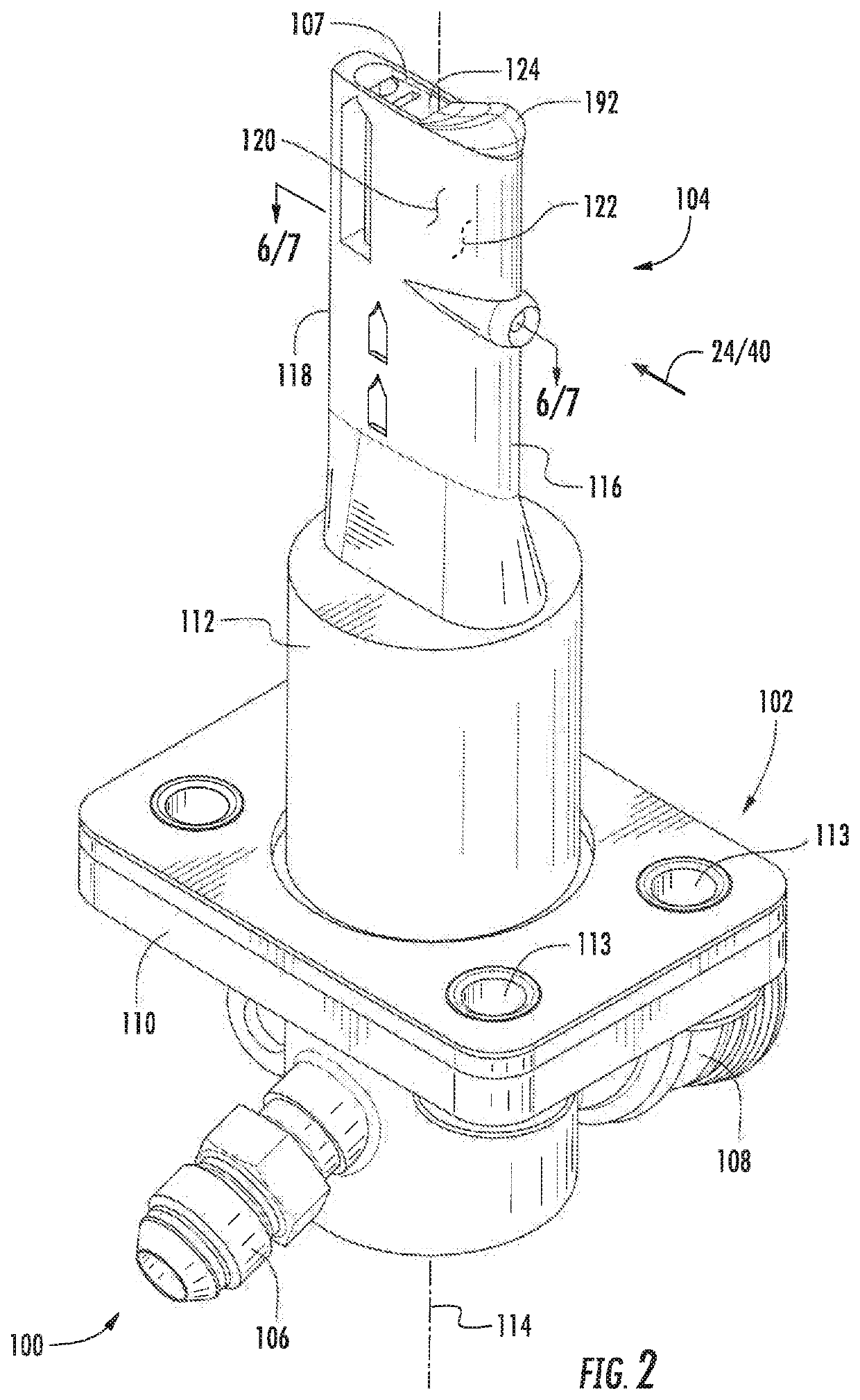
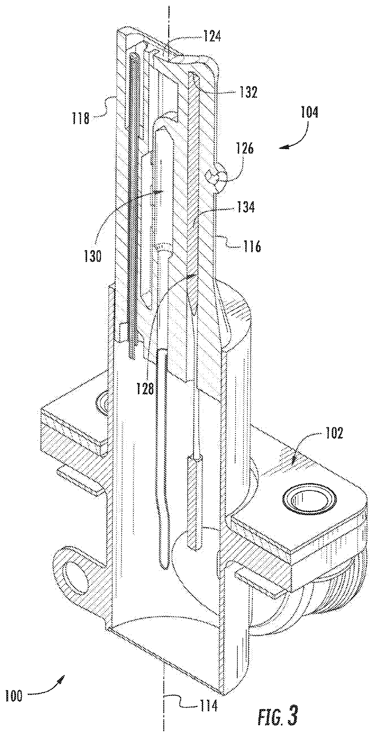
[0038]Reference will now be made to the drawings wherein like reference numerals identify similar structural features or aspects of the subject disclosure. For purposes of explanation and illustration, and not limitation, a partial view of a pressure and temperature sensor 100 in accordance with the disclosure is shown in FIG. 1 and is designated generally by reference character 100. Other embodiments of sensors, sensor assemblies, methods of removing entrained ice from within air entering sensors, and methods of making sensors and sensor assemblies are provided in FIGS. 2-19, as will be described. The sensors and sensors assemblies described herein can be used for measuring pressure and temperature of air in icing conditions, such as with P2T2 probes on aircraft, though the present disclosure is not limited to P2T2 probes or to pressure and temperature sensing on aircraft in general.

[0039]Referring to FIG. 1, an aircraft 10 is shown. The aircraft 10 includes a gas turbine engine 12...


PUM

PropertyMeasurementUnit
pressureaaaaaaaaaa
temperatureaaaaaaaaaa
slowing velocityaaaaaaaaaa

Abstract

A sensor includes a mount arranged along a sensor axis, an airfoil body fixed to the mount and having a first face and second face extending along the sensor axis, a heater element, and a temperature probe. The heater element and the temperature probe are positioned within the airfoil body and extend axially along the airfoil body. The airfoil body defines within its interior a pressure channel having an inlet segment extending between the heater element and the first face of the airfoil body to prevent ice formation and / or melt ice entrained within air traversing the pressure channel. Gas turbine engines, methods of removing ice or preventing ice formation, and methods of making sensors are also described.

Description

BACKGROUND[0001]The present disclosure is generally related to pressure and temperature measurement, and more particularly to removing ice entrained within air ingested in sensors used to measure pressure and temperature in gas turbine engines.[0002]Gas turbine engines, such as carried by aircraft, commonly employ sensors. The sensors are generally employed to monitor parameters that can influence performance of the gas turbine engine. For example, temperature sensors may be employed to measure temperature of air entering the compressor section of the gas turbine engine. Pressure sensors may alternatively (or additionally) be employed to measure pressure of airstream entering the compressor section of the gas turbine engine. Such sensors typically employ a probe, which protrudes into the airstream entering the compressor section to monitor engine operating condition and / or to control operation of the gas turbine engine.[0003]In some operating environments, such as during flight in i...

Claims


Application Information

Patent Timeline
Patent Type & Authority Applications(United States)
IPC IPC(8): F01D25/02F01D21/12G01K13/02
CPCF01D25/02F01D21/12F01D21/003G01K2013/024G01K13/02F01D17/08F01D17/085F02C7/047G01K13/028G01L19/0092G01M15/14F01D25/10G01K13/024
Inventor HOLL, ANDREWWIGEN, SCOTTSABLE, ROBERT EDWARDISEBRAND, SCOTT D.BOYD, BRIAN
Owner ROSEMOUNT AEROSPACE
Why Eureka
Try Eureka