CVD apparatus

a technology of cvd apparatus and cvd light, which is applied in the direction of coatings, chemical vapor deposition coatings, metallic material coating processes, etc., can solve the problems of reducing yield, producing dust particles, and affecting the effect of production efficiency

Inactive Publication Date: 2005-05-17
ANELVA CORP
View PDF27 Cites 229 Cited by
  • Summary
  • Abstract
  • Description
  • Claims
  • Application Information

AI Technical Summary

Benefits of technology

[0016]The present invention is to overcome the above problems and to provide a CVD apparatus that can be used effectively for the deposition of films on large-surface substrates. The apparatus can be used in cases in which silicon oxide films are deposited on large-surface substrates according to plasma-enhanced CVD by using a reactive gas such as silane in the production of large liquid crystal displays that use low temperature polysilicon type TFTs. For this, the plasma-enhanced CVD apparatus is configured so as to minimize the probability of contact between plasma and a reactive gas in a stage prior to the film deposition, sufficiently suppressing formation of dust particles, avoiding implantation of ions into the substrate, and allowing radicals to be distributed sufficiently in the vicinity of the substrate.

Problems solved by technology

When using a conventional plasma-enhanced CVD apparatus, problems may arise when high-energy ions are implanted on film deposition surfaces from the plasma existing in the front-surface space of the substrate.
In addition, since the reactive gas is fed directly in the plasma, the reactive gas and oxygen react vigorously, producing dust particles.
This causes a problem in that the yield is reduced.
Therefore, problems arise in that the deposition speed is reduced, and the distribution of the radicals is not suitable in the vicinity of the surface of the substrate.
Particularly, the fact that the distribution of the radicals is not suitable has given rise to a problem in that the capacity does not meet requirements for large-surface substrates used for large liquid crystal displays.
In the plasma-enhanced CVD apparatus disclosed in Japanese Unexamined Patent Publication No. 5-21393 also, the determined dimensions of the through-holes formed in the mesh plate are such that the reactive gas may diffuse back into the plasma-generating space, causing the same problem as in the above case.
However, there is no description regarding a configuration that will avoid a possibility that the reactive gas which has been fed into the plasma-processing chamber so as not to contact the plasma will diffuse back into the plasma-generating chamber through the plurality of openings formed in the mesh plate.
Therefore, there is a possibility that the reactive gas will enter into the plasma-generating chamber through the mesh plate, causing chemical reactions with the plasma.
Also, because of the separation by the partitioning wall section, movement of the reactive gas fed into the film deposition process space into the plasma-generating space is restricted sufficiently.

Method used


Image

  • CVD apparatus
  • CVD apparatus
  • CVD apparatus

Examples


Embodiment Construction

[0029]Preferred embodiments of the present invention are described below with reference to the attached drawings.

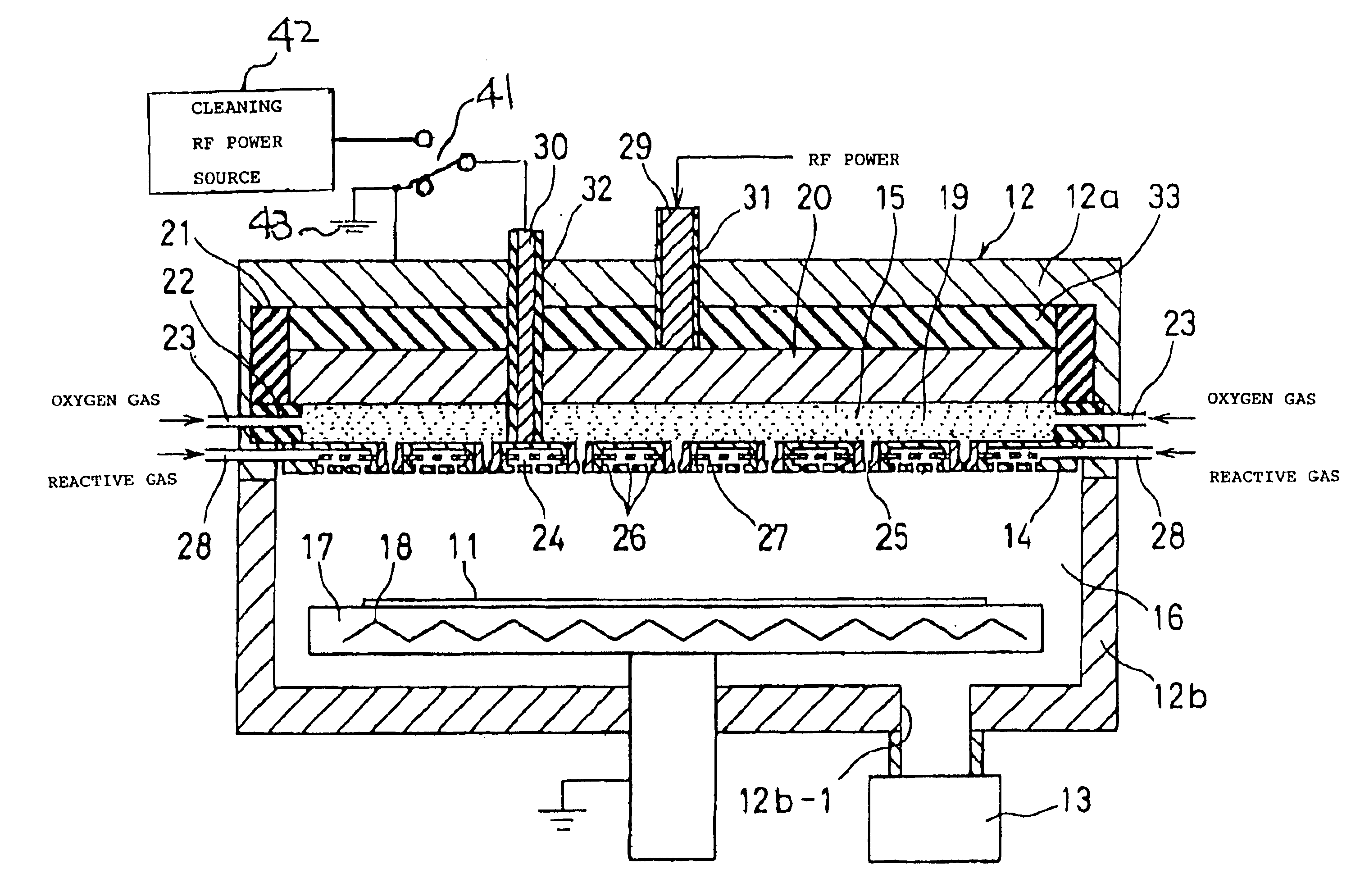
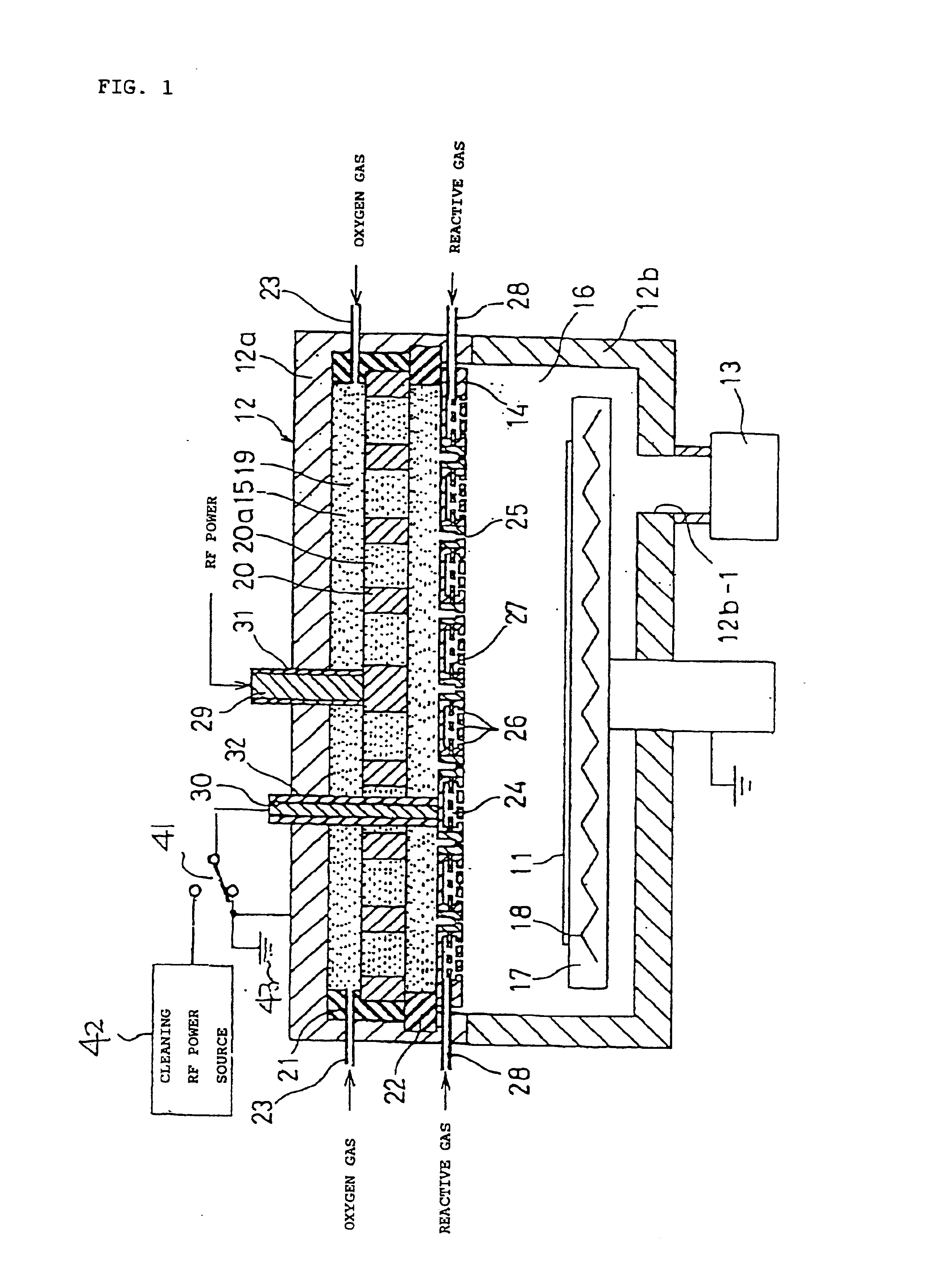
[0030]In FIG. 1, in the CVD apparatus, silane is preferably used as the reactive gas, and a silicon oxide film is deposited on an upper surface of a glass substrate 11 for a standard TFT as a gate insulating film. A vacuum vessel 12 of the plasma CVD apparatus is maintained in a predetermined vacuum state by use of an exhaust mechanism 13 for deposition of the film. The exhaust mechanism 13 is connected to a discharging port 12b-1 formed in the vacuum vessel 12.

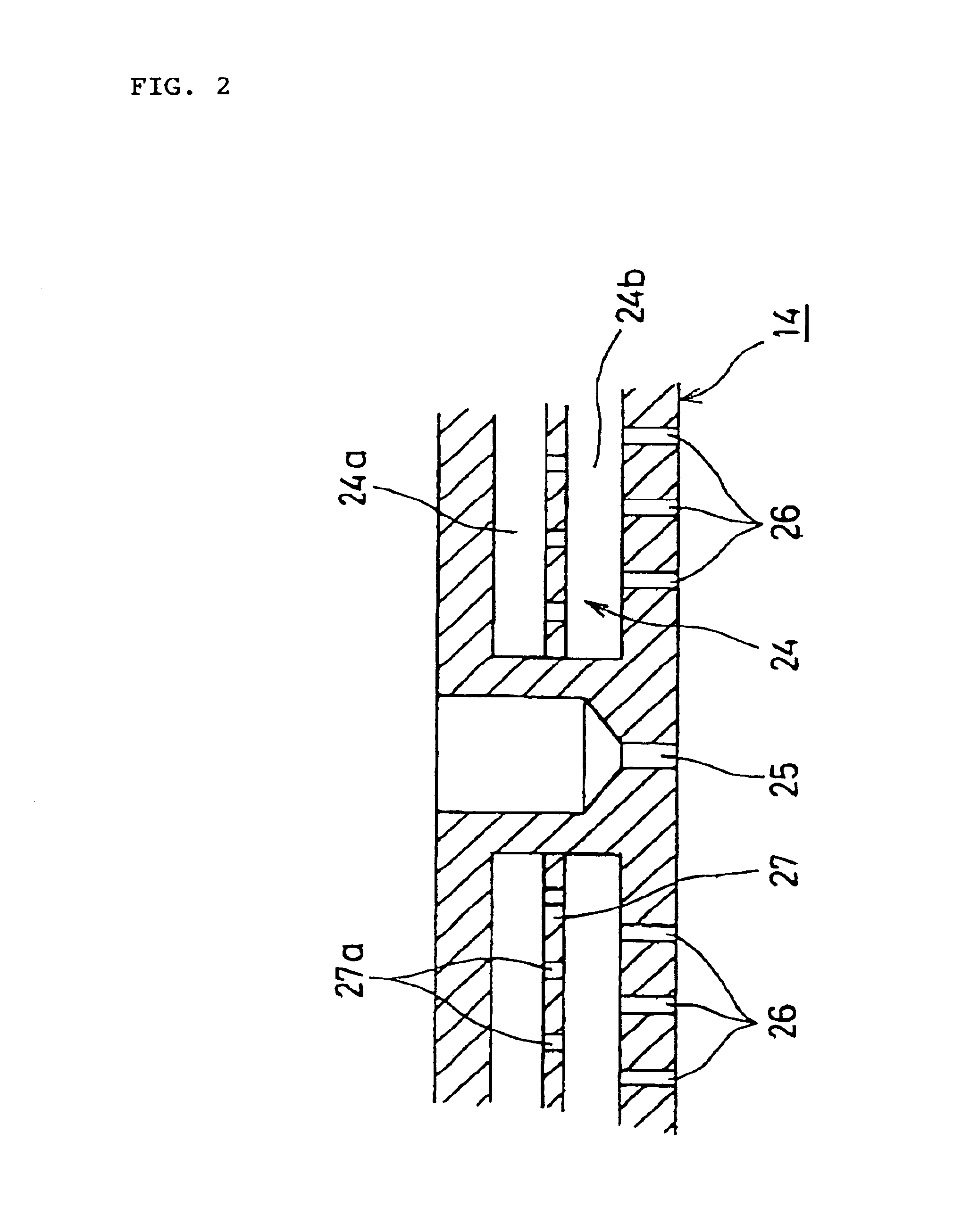
[0031]In the vacuum vessel 12, a partitioning wall section 14, made of an electrically conductive material, is arranged in a horizontal state. The partitioning wall section 14 of which the shape is, for example, circular in plan view, is arranged in a manner such that a peripheral section thereof is pressed down by a bottom surface of a lower insulating member 22 so as to form a seal between the vacuum vessel 12 an...


PUM

PropertyMeasurementUnit
temperaturesaaaaaaaaaa
temperatureaaaaaaaaaa
pressureaaaaaaaaaa

Abstract

A CVD apparatus produces plasma to generate radicals and uses the radicals, silane, and the like so as to deposit films on substrates in a vacuum vessel 12. The vacuum vessel has a partitioning wall section 14 for separating the inside thereof into a plasma-generating space 15 and a film deposition process space 16. The partitioning wall section has a plurality of through-holes 25 and diffusion holes 26. An interior space 24 receives the silane or the like fed into the film deposition process space through diffusion holes 16. The radicals produced in the plasma-generating space are fed into the plasma-generating space through the through-holes. The through-holes satisfy the condition of uL/D>1, where u represents the gas flow velocity in the through-holes, L represents the effective length of the through-holes, and D represents the inter-diffusion coefficient.

Description

CROSS-REFERENCE TO RELATED APPLICATIONS[0001]This application is a continuation application of U.S. Ser. No. 09 / 435,625, filed on Nov. 8, 1999, and U.S. Ser. No. 09 / 255,852, filed on Feb. 23, 1999, now U.S. Pat No. 6,245,396 the entire contents of both applications are hereby incorporated herein by reference. This application also claims the priority of Japanese Patent Application No. 11-157692, filed in Japan on Jun. 4, 1999; Japanese Patent Application No. 11-23887, filed in Japan on Feb. 1, 1999; and Japanese Patent Application No. 10-62066, filed in Japan on Feb. 26, 1998; the entire contents of which are hereby incorporated herein by reference.BACKGROUND OF THE PRESENT INVENTION[0002]1. Field of the Invention[0003]The present invention relates to a CVD apparatus, and particularly, to a CVD apparatus suitable for depositing films on large flat-panel substrates.[0004]2. Description of the Related Art[0005]Conventionally, known production methods for large liquid crystal displays ...

Claims


Application Information

Patent Timeline
Patent Type & Authority Patents(United States)
IPC IPC(8): C23C16/448C23C16/452C23C16/455H01L21/02H01L21/316
CPCC23C16/452C23C16/455H01L21/31612H01L21/02274H01L21/02164
Inventor XU, GENOGAMI, HIROSHI
Owner ANELVA CORP
Why Eureka
Try Eureka