
Axially split pump

An axial and split technology, applied in the direction of radial flow pumps, pumps, pump components, etc., can solve the problems of reduced pump efficiency and environmental pollution, and achieve the effects of simple installation, simple manufacture, and good sealing effect

Active Publication Date: 2016-06-15
SULZER MANAGEMENT AG
View PDF6 Cites 4 Cited by
  • Summary
  • Abstract
  • Description
  • Claims
  • Application Information

AI Technical Summary

Problems solved by technology

Leakages present here not only lead to a reduction in the efficiency of the pump but, depending on the fluid delivered by the pump, can also lead to environmental pollution by the escaping fluid, e.g. considering liquids such as petroleum or crude oil

Method used


Image

  • Axially split pump
  • Axially split pump
  • Axially split pump

Examples


Embodiment Construction

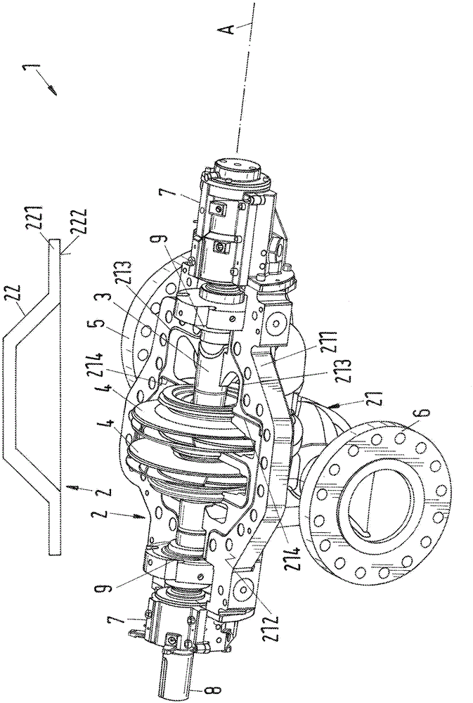
[0042] figure 1 An embodiment of the axially split pump according to the invention, indicated generally by reference number 1 , is shown in a perspective view. The pump 1 comprises a housing 2 which is split axially and has a bottom 21 and a cover 22 . For better understanding, cover 22 is in figure 1 removed and indicated only symbolically. image 3 A top view of the bottom 21 of the housing 2 of this embodiment is shown.

[0043] The housing 2 comprises an inlet 5 for taking in the fluid to be delivered and an outlet 6 for the fluid. The pump 1 also comprises a rotatable shaft 3 , the longitudinal direction of which defines the axial direction A . Mounted rotatably fixed at the shaft 3 is at least one impeller 4 , in the present case two impellers 4 conveying the fluid from the inlet 5 to the outlet 6 . Furthermore, corresponding bearing arrangements 7 are provided at both ends with respect to the axial direction A of the pump 1 in order to support the shaft 3 of the pu...


PUM


Abstract

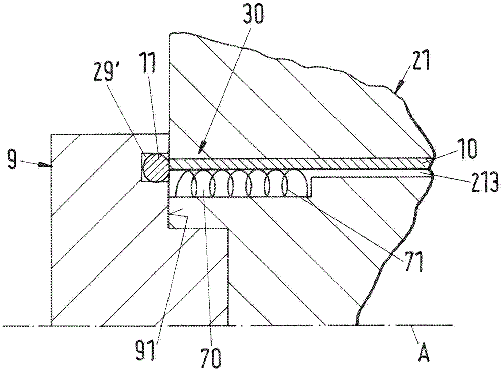
An axially split pump for conveying a fluid is suggested having an axially split housing (2) which comprises a bottom part (21) and a cover (22), wherein the bottom part (21) has a first sealing surface (212) and the cover (22) has a second sealing surface (222), wherein the bottom part (21) and the cover (22) can be fastened to one another in such a way that the two sealing surfaces (212, 222) have a direct contact with one another, wherein at least one first sealing groove (213) for the reception of a first sealing element (10) is provided in the sealing 10 surfaces (212, 222), and wherein at least a second sealing groove (29; 29'; 214) is provided for the reception of a second sealing element, wherein the first sealing groove (213) and the second sealing groove (29; 29'; 214) are connected to one another through a connection region (30) and wherein an elastic pre-loading ele ment (71) is provided in the connection region (30), which exerts a pre-load onto 15 one of the two sealing elements (10, 11, 12).

Description

technical field [0001] The invention relates to an axially split pump for conveying fluids according to the preambles of the independent claims. Background technique [0002] Axially split pumps, which are also called horizontally split pumps, are pumps in which the casing is split parallel to the axis of the shaft and thus has a bottom and a cover. The base and the cover each have flanges which are placed one on top of the other for mounting the pump and are then fixedly connected to each other, for example screwed to each other. [0003] Axially split pumps have been known for a long time and are manufactured in a wide variety of embodiments, typically as centrifugal pumps, for example as unidirectional or bidirectional pumps and as into single-stage pumps or multi-stage pumps. In this respect, the impeller of the pump can be arranged between two bearings (inter-bearing pump). Furthermore, the fields of application of these pumps are very wide, for example they are used...

Claims


Application Information

Patent Timeline
Patent Type & Authority Applications(China)
IPC IPC(8): F04D1/06F04D29/08
CPCF04D1/06F04D29/426F04D29/628F16J15/06F04D29/086F16J15/062F04D17/08F04D29/083F04D29/22F04D29/28F04D29/4206F04D29/624
Inventor T.维斯钦格H.蒂施勒B.沃格
Owner SULZER MANAGEMENT AG
Learn More