Heat exchanger with flat tubes

a technology of heat exchanger and flat tube, which is applied in the direction of tubular elements, heat exchanger fins, stationary conduit assemblies, etc., can solve the problems of deteriorating the heat exchange efficiency of the heat exchanger, maximizing the heat transfer efficiency at the front end portion of the tube,

Inactive Publication Date: 2006-06-13
LG ELECTRONICS INC
View PDF14 Cites 19 Cited by
  • Summary
  • Abstract
  • Description
  • Claims
  • Application Information

AI Technical Summary

Benefits of technology

[0019]A first object of the present invention is to provide a heat exchanger with flat tubes each having multiple channels that have different refrigerant flow capacities from each other.
[0020]A second object of the present invention is to provide a heat exchanger with flat tubes each having multiple channels, in which the capacities of the multi-channels are increased or decreased at a predetermined rate according to a direction where exterior air flows.
[0021]A third object of the present invention is to provide a heat exchanger with flat tubes each having multi-channels, in which widths of the multi-channels are designed to increase or decrease a refrigerant flow capacity in response to a flow capacity of exterior air.
[0022]A fourth object of the present invention is to provide a heat exchanger with flat tubes each having multiple channels, in which a width of a foremost channel among the channels is broadest and a width of a rearmost channel among the channels is narrowest.
[0023]A fifth object of the present invention is to provide a heat exchanger with flat tubes each having multiple channels, in which adjacent channels among the channels have different widths.
[0024]A sixth object of the present invention is to provide a heat exchanger with flat tubes each having multiple channels, in which widths of the channels are decreased at a predetermined rate in a direction where exterior air flows.
[0025]A seventh object of the present invention is to provide a heat exchanger with flat tubes each having multiple channels each channel being provided at an inner circumference with a plurality of grooves.
[0026]An eighth object of the present invention is to provide a heat exchanger with flat tubes each provided at portions that do not contact cooling fins with ridge-shaped projections.

Problems solved by technology

However, since the widths of channels are identical to each other and the intervals between the channels are also identical, it is difficult to maximize the heat transfer efficiency at a front end portion of the tube, thereby deteriorating the heat transfer efficiency of the heat exchanger.

Method used


Image

  • Heat exchanger with flat tubes
  • Heat exchanger with flat tubes
  • Heat exchanger with flat tubes

Examples


Embodiment Construction

[0048]Reference will now be made in detail to the preferred embodiments of the present invention, examples of which are illustrated in the accompanying drawings. Wherever possible, the same reference numbers will be used throughout the drawings to refer to the same or like parts.

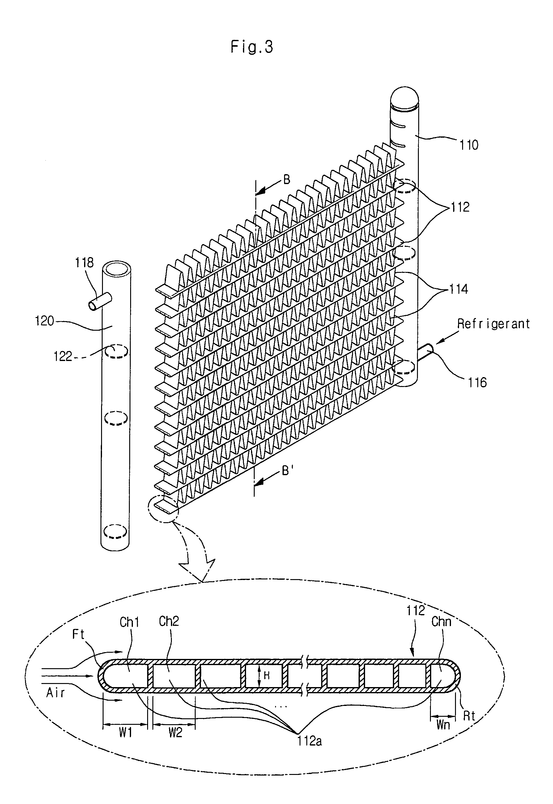
[0049]FIG. 3 shows a perspective view of a heat exchanger with flat tubes according to an embodiment of the present invention.

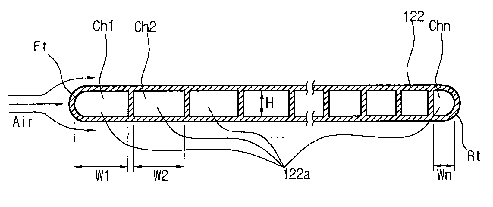
[0050]As shown in FIG. 3, the inventive heat exchanger includes: first and second header tanks 110 and 120; a plurality of flat tubes 112 arranged in parallel and spaced apart from each other at an identical distance between the first and second header tanks 110 and 120, each of the flat tubes 112 having a plurality of refrigerant flow holes 112a defined by a plurality of channels Ch1–Chn having different capacities from each other to allow refrigerant to disperse and flow to the first and second header tanks 10 and 20; and cooling fins 114 disposed between the flat tubes 112 to radia...


PUM


Abstract

A heat exchanger including first and second header tanks for receiving and discharging refrigerant. Further, the first and second header tanks are spaced apart from each other by a predetermined distance. Also include is a plurality of flat tubes each having opposite ends respectively connected to the first and second header tanks, in which each of the flat tubes has channels through which the refrigerant scatters and flows, and the channels have a different capacity from each other. Further included is a cooling member for discharging heat of the refrigerant flowing along the flat tubes.

Description

[0001]This Non-provisional application claims priority under 35 U.S.C. § 119(a) on Patent Application No(s). 10-2003-0061858 filed in Korea on Sep. 4, 2003, the entire contents of which are hereby incorporated by reference.BACKGROUND OF THE INVENTION[0002]1. Field of the Invention[0003]The present invention relates to a heat exchanger with flat tubes, and more particularly, to a heat exchanger with flat tubes that can improve the heat exchange efficiency by making capacities of channels of each flat tube different from each other.[0004]2. Description of the Related Art[0005]Generally, an air conditioner for cooling interior air using a cooling cycle includes a compressor for compressing refrigerant to a high pressure, a condenser for exchanging heat of the compressed refrigerant with exterior air to liquefy refrigerant gas, and an evaporator for exchanging heat of the liquefied refrigerant with the interior air using an expansion valve or capillary tubes to evaporate the liquefied r...

Claims


Application Information

Patent Timeline
Patent Type & Authority Patents(United States)
IPC IPC(8): F28F1/40F28F1/42F28F1/32F28D1/053F28F1/02F28F1/12F28F1/24
CPCF28D1/05391F28F1/022F28F1/24F28F1/126F28F2215/04F28F1/32
Inventor CHIN, SIM WONHONG, KEE SOOCHUNG, MOON KEE
Owner LG ELECTRONICS INC
Why Eureka
Try Eureka