
Mobile transceiver and electronic module for controlling the transceiver

Active Publication Date: 2006-06-13
PHONAK COMM
View PDF8 Cites 204 Cited by
  • Summary
  • Abstract
  • Description
  • Claims
  • Application Information

AI Technical Summary

Benefits of technology

[0003]It is an object of this invention to provide a mobile transceiver, comprising a receiver for receiving electrical or electromagnetic signals carrying audio signals and a radio transmitter for transmitting radio signals carrying audio signals, and an electronic module controlling the mobile transceiver, which do not have the disadvantages of the prior art. In particular, it is an object of the present invention to provide a mobile transceiver and an electronic module controlling the transceiver which can be used with audio signals from different types of audio sources and which make it possible for users to differentiate audio signals from different audio sources.

Problems solved by technology

The known mobile transceivers are typically limited, however, to specific applications rendering them not very useful for the hearing impaired who are exposed daily to a multitude of different acoustic information from various audio sources.
The known mobile transceivers cannot be used in connection with different types of audio sources.
Moreover, the known mobile transceivers do not assist their users in differentiating audio signals from different audio sources.
Particularly, hearing impaired people get drowned in acoustic information from numerous audio sources, without being able to make out individual audio sources or to differentiate acoustic information from different audio sources.
Consequently, the ringing of a telephone, or worse a fire alarm, might get missed because of audio signals from a television or stereo set.

Method used


Image

  • Mobile transceiver and electronic module for controlling the transceiver
  • Mobile transceiver and electronic module for controlling the transceiver
  • Mobile transceiver and electronic module for controlling the transceiver

Examples


Embodiment Construction

[0022]In the following description the term audio signal refers to acoustic signals audible to humans, typically in the range of 100 Hz to 8 KHz or, in the case of high fidelity electronic devices, in the extended range of 20 Hz to 20 KHz.

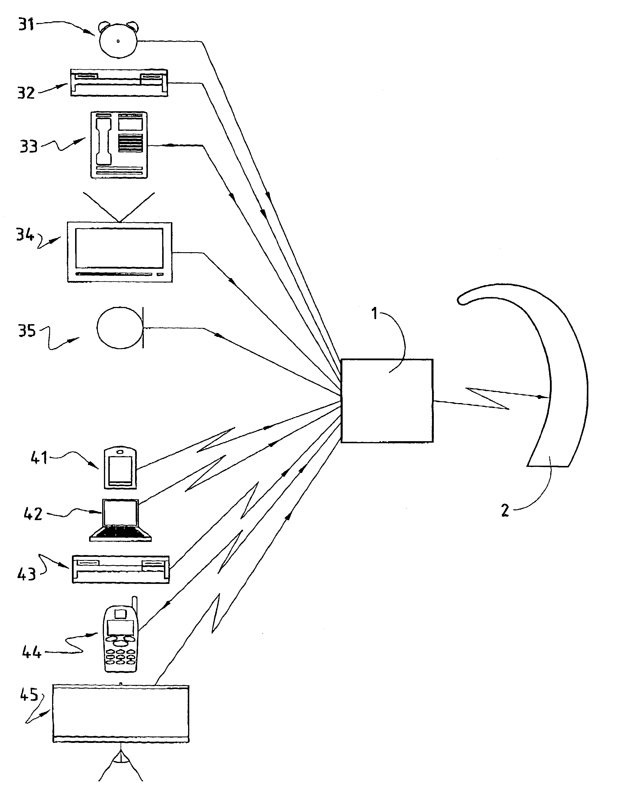
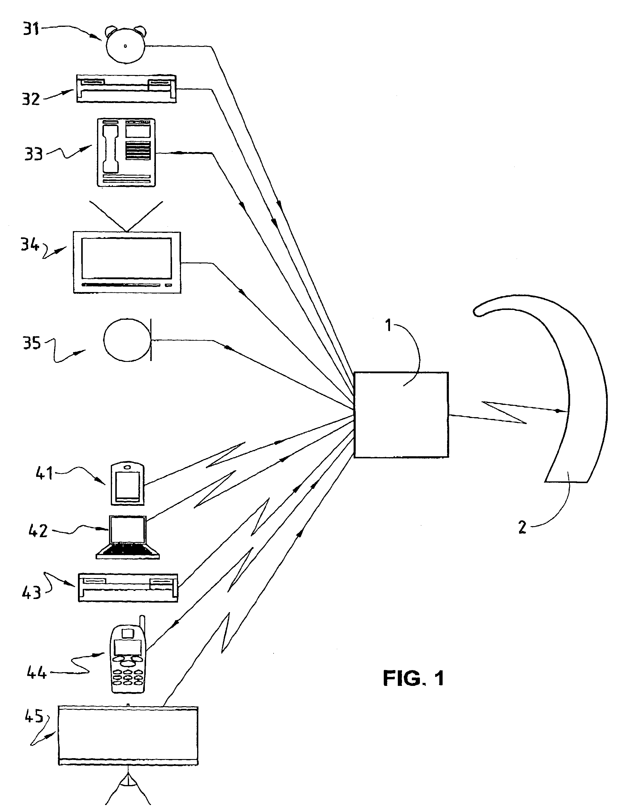
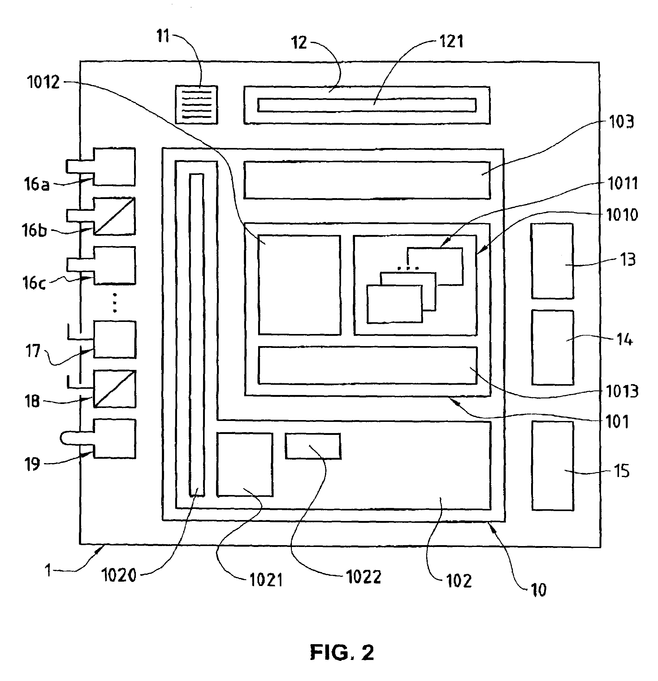
[0023]In FIG. 1, the reference numeral 1 refers to a mobile transceiver which will be described later in more detail with reference to FIG. 2. The mobile transceiver 1 is designed such that it can be carried easily by its user and, depending on the situation, the user may place the mobile receiver 1 on a platform away from himself or carry the mobile receiver 1 on him, for example. Obviously, the mobile receiver 1 can also be installed permanently in, or connected permanently to, a fixed or mobile electronic device.

[0024]In FIG. 1, the reference numerals 31, 32, 33, 34, 35 refer to examples of different audio sources which are connected to the mobile transceiver 1 by means of wired links. The reference numeral 31 refers to an audio source generatin...


PUM


Abstract

A mobile transceiver (1) comprises several receivers (16a, 16b, 16c, 17, 18, 19) for receiving electrical or electromagnetic signals carrying audio signals and a radio transmitter (15) for transmitting radio signals carrying audio signals. The mobile transceiver (1) comprises a prioritizing module (101) for assigning priority values to audio signals received by the receivers (16a, 16b, 16c, 17, 18, 19). The prioritizing module (101) is designed to assign priority values in accordance with priority values assigned to the receivers (16a, 16b, 16c, 17, 18, 19) that received the audio signal concerned and / or to signal identifiers contained in the received electrical or electromagnetic signals carrying the audio signal concerned. The mobile transceiver (1) makes it possible to receive several audio signals separately from different audio sources, to prioritize automatically the received audio signals, and to select automatically and transmit one of the several received audio signals to the user, thereby assisting the possibly hearing impaired user in differentiating audio signals from different audio sources.

Description

BACKGROUND OF THE INVENTION[0001]The present invention relates to a mobile transceiver and to an electronic module controlling the transceiver. Specifically, the present invention relates to a mobile transceiver and to an electronic module controlling the transceiver, the mobile transceiver comprising a receiver for receiving electrical or electromagnetic signals, the electrical or electromagnetic signals carrying audio signals, and a radio transmitter for transmitting radio signals carrying audio signals.[0002]Transceivers with a receiver for electrical signals carrying audio signals and with a radio transmitter for transmitting radio signals carrying audio signals are known for the wireless transfer of acoustic information between separate locations. Such known transceivers have a connector for connecting a microphone to the receiver of the transceiver. The electrical signal carrying the audio signal received from the connected microphone is forwarded to the radio transmitter of t...

Claims


Application Information

Patent Timeline
IPC IPC(8): H04H7/00H04H60/04H04B1/20H04R25/00
CPCH04B1/20H04R25/554H04R2225/55
Inventor GERBER, LOUISGYSIN, STEFAN
Owner PHONAK COMM
Learn More