Container including a bowl and a lid each having interfitting lips

a technology of inter-fitting lips and containers, which is applied in the direction of containers, liquid handling, applications, etc., can solve the problems of virtually unusable, difficult to achieve excellent sealing with inexpensive containers, and high quality containers can be so expensiv

Inactive Publication Date: 2006-06-20
SC JOHNSON & SON INC
View PDF31 Cites 87 Cited by
  • Summary
  • Abstract
  • Description
  • Claims
  • Application Information

AI Technical Summary

Benefits of technology

[0013]In another aspect of the invention, a method of securing a bowl to a lid comprises the step of placing a lid, comprising a main body portion and a lid lip on a periphery of the main body portion, onto a bowl comprising a base, a sidewall extending from the base and a bowl lip extending from the sidewall, the sidewall defining an opening. The method further comprises the step of sliding an inner hook and an outer hook disposed on the lid lip along inner and outer walls of the bowl lip, engaging the outer hook with an outer undercut formed in the bowl lip, contacting a seal ring with a top of the bowl lip, and engaging the inner hook with an inner undercut formed in the bowl lip. The engagement of the inner and outer hooks with the inner and outer undercuts secures the bowl to the lid.

Problems solved by technology

However, these high quality containers can be so expensive that they are virtually unusable for fear of losing them.
Excellent sealing is difficult to achieve with the inexpensive containers, however, because such containers are typically mass-produced, such as in a thermoforming process, using inexpensive materials such as polypropylene.
With regard to the seal, U.S. Pat. No. 6,170,696 to Tucker, et al. discloses a “nearly leak tight seal.” The seal in that patent, however, can be difficult to manufacture successfully.
This arrangement makes manufacturing tolerances a significant concern, because if any single surface is too long or too short, the other surfaces will not fit together properly.

Method used


Image

  • Container including a bowl and a lid each having interfitting lips
  • Container including a bowl and a lid each having interfitting lips
  • Container including a bowl and a lid each having interfitting lips

Examples


first embodiment

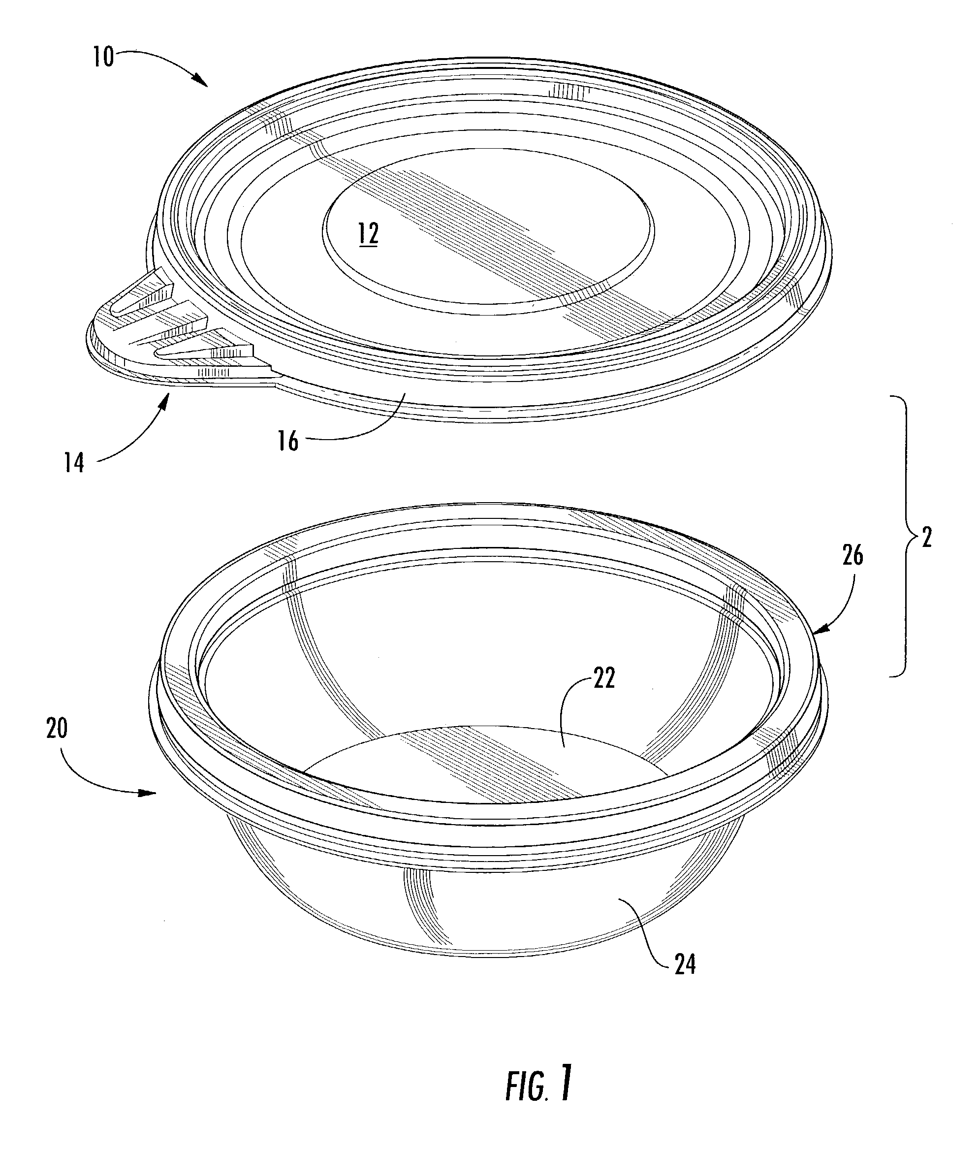
[0029]FIG. 1 is an exploded, perspective view of a container 2 according to the invention. The container 2 generally comprises a lid 10 and a bowl 20, which are preferably made of a resilient material, such as polypropylene. The lid is preferably about 15 to about 25 mils (38–64 thousandths of a centimeter), inclusive, in thickness, and most preferably about 20 mils (51 thousandths of a centimeter) in thickness. The bowl is preferably about 30 mils (76 thousandths of a centimeter) in thickness. Of course, the lid and the bowl may be thicker or thinner, as costs dictate.

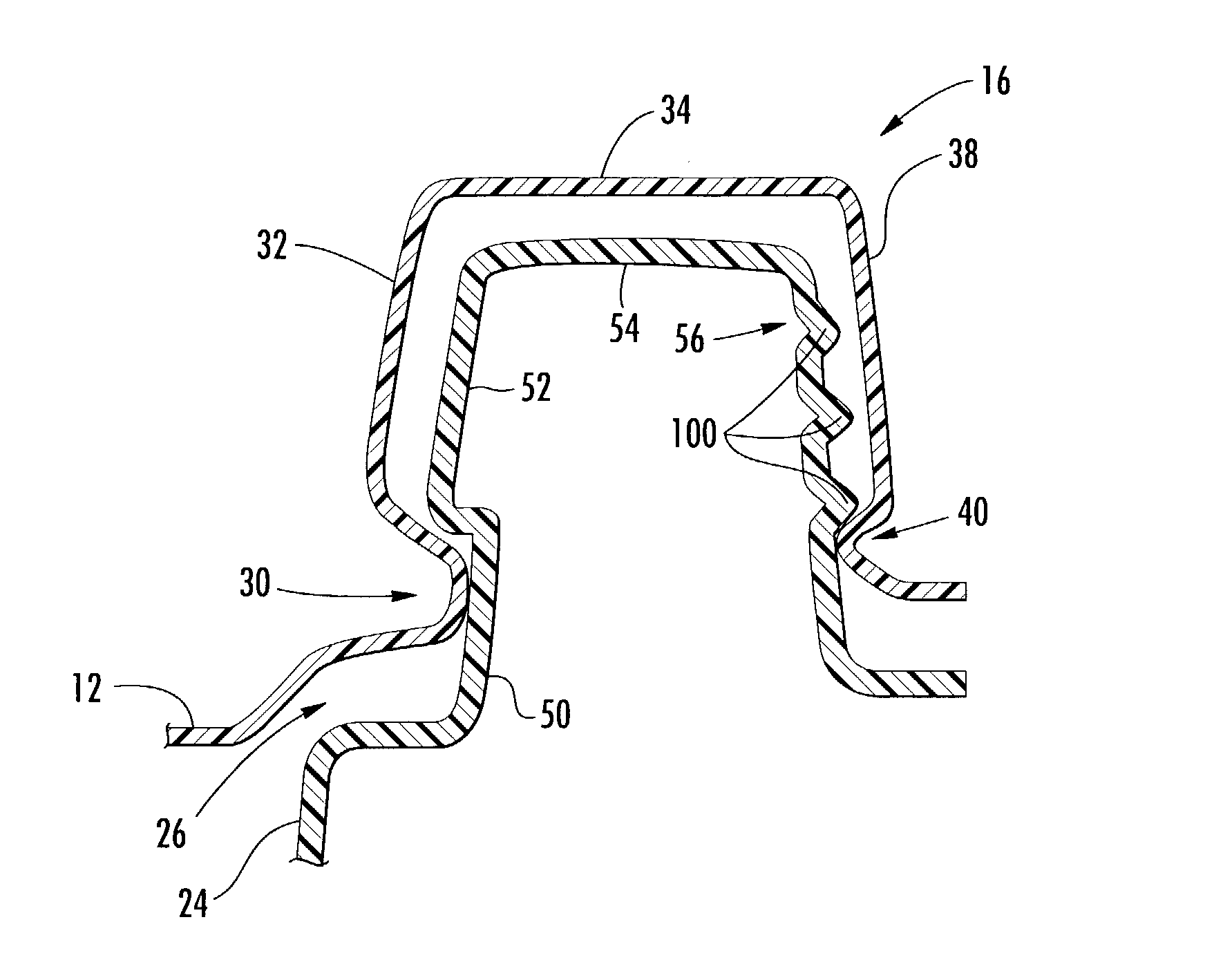
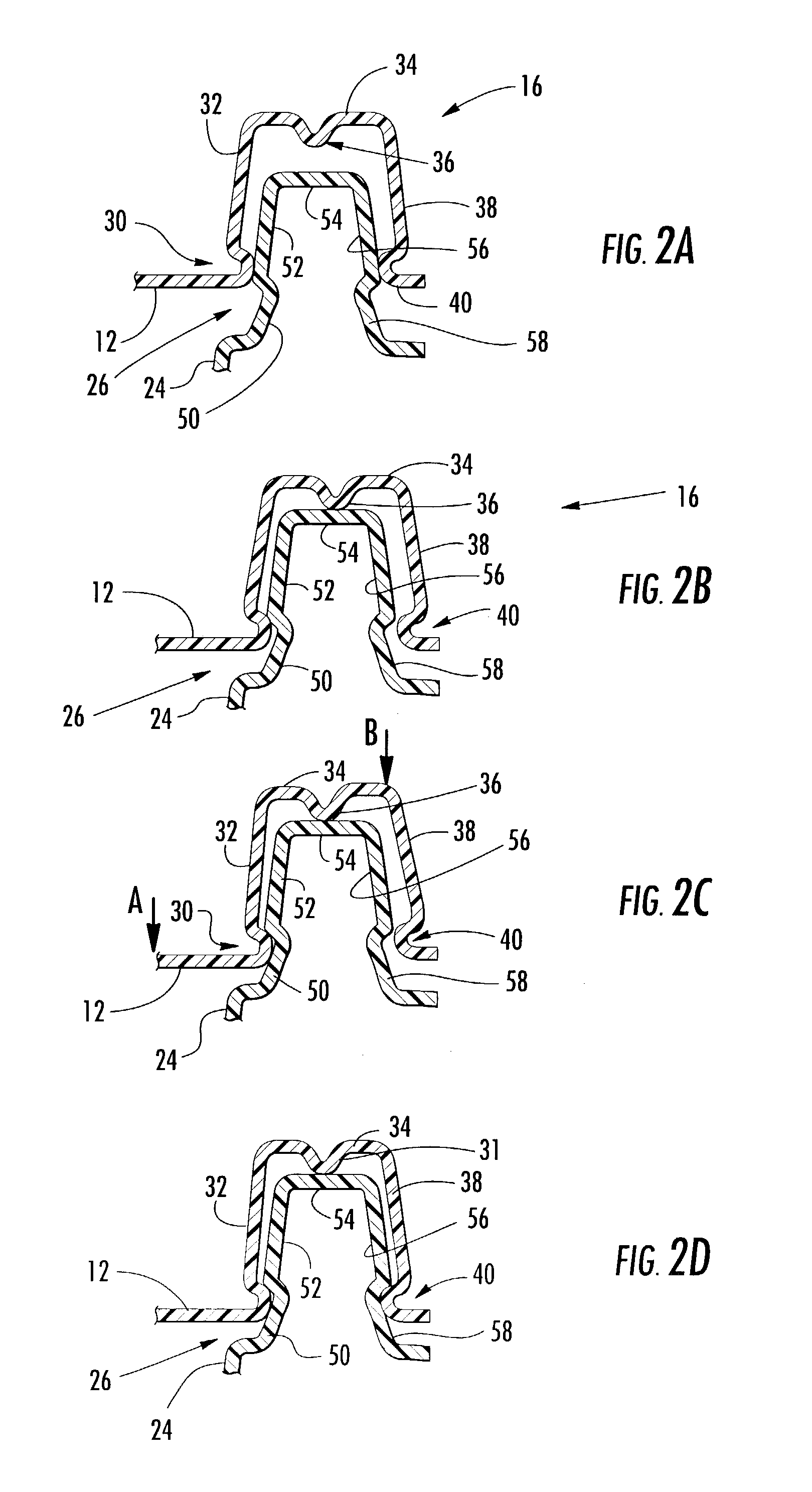
[0030]As shown in FIGS. 1 and 2A–2D, the lid 10 includes a generally planar main body portion 12, a tab 14 and a lid lip 16 having generally the shape of an inverted U. The bowl 20 includes a generally planar base 22, an upwardly and outwardly extending sidewall 24 defining an opening, and a bowl lip 26 adapted to interfit with the lid lip 16. As will be described in more detail below, the engagement between the bowl ...

fourth embodiment

[0042]As shown in FIGS. 5A–5C, in the fourth embodiment, the inner and outer hooks 30, 40 slide along the walls 52, 56 of the bowl lip 26 as the lid is pressed down on the bowl. When the inner hook 30 is just above the inner undercut 50, as shown in FIG. 5C, the sealing ring 36 contacts or nearly contacts the inner wall 52. As shown in FIG. 5D, when the lid is fully engaged with the bowl, the inner hook engages the inner undercut 50 and the sealing ring 36 is brought into firm contact with the inner wall 52 by virtue of the clamping action between the inner and outer hooks 30, 40.

[0043]FIG. 6 shows a fifth embodiment that is the same as the fourth embodiment in all aspects except that the single undercut is placed on the outside of the bowl lip 26 and the seal ring 36 is placed on the outside wall 38 of the lid lip 16.

[0044]In each of the foregoing embodiments, either of the inner hooks 30 or the outer hooks 40 may be continuous or intermittent. Likewise, the inner and outer undercu...

sixth embodiment

[0049]In the sixth embodiment, to the extent that the spring formation 202 buckles, the spring formation 202 increases resistance to opening from pressure coming from the bottom of the lid. Such pressure may be generated by food in the container pressing upon the bottom of the lid. However, such buckling that increases the resistance to opening would not occur when a force is applied from a different direction, such as, for example, when a user presses up on the tab 14 shown in FIG. 1 to remove the lid from the bowl. Therefore, the spring formation 202 would not increase the difficulty of intentionally removing the lid from the bowl.

[0050]The process of engaging the lid lip 200 with the bowl lip 250 of the sixth embodiment is best illustrated with reference to FIGS. 7 and 8. As shown in FIG. 8, when the lid is placed on the bowl, the lead-in portion 203 rests against the bowl lip 250 where the top 254 intersects the undercut 252. It should be understood that the bowl lip 250 may not...


PUM

PropertyMeasurementUnit
thicknessaaaaaaaaaa
thicknessaaaaaaaaaa
thicknessaaaaaaaaaa

Abstract

A container (2) includes a bowl (20) and a lid (10). The lid (10) includes a lid lip (16) having a generally inverted U-shape and the bowl (20) includes a bowl lip (26) having a generally inverted U-shape such that the lid lip (16) and the bowl lip (26) interfit, forming mutually opposing surfaces, with the lid lip (16) superposing the bowl lip (26). At least one of the bowl lip (26) and the lid lip (16) includes a seal in firm contact with the opposing surface, with the seal contacting the opposing surface in a small area relative to a total surface area of the bowl lip (26).

Description

BACKGROUND OF THE INVENTION[0001]1. Field of the Invention[0002]This invention relates to a container comprising a bowl and a lid and, in particular, a container comprising a bowl and a lid each having interfitting lips.[0003]2. Description of the Background of the Invention[0004]Consumers have a variety of food storage needs, including storing leftover solid foods such as lasagna, semi-solid foods such as stews, and liquids such as soups. Containers for storing items such as these foods come in a variety of shapes, sizes and levels of quality. Typically, however, the container includes a bowl or other receptacle and a lid that fits on the bowl and seals the bowl in some way. High quality containers exhibit excellent sealing characteristics, such that even soups will not spill out of the container regardless of the orientation of the container. However, these high quality containers can be so expensive that they are virtually unusable for fear of losing them.[0005]There has been an ...

Claims


Application Information

Patent Timeline
Patent Type & Authority Patents(United States)
IPC IPC(8): B65D41/16B65D43/02
CPCB65D43/0208B65D43/0212B65D43/021B65D2543/0099B65D2543/00092B65D2543/00296B65D2543/00509B65D2543/00555B65D2543/0062B65D2543/00648B65D2543/00685B65D2543/00731B65D2543/0074B65D2543/00796B65D2543/00842B65D2543/00953
Inventor STANOS, LAWRENCE C.ZETTLE, JEFFREY J.EVERS, JR., PETER T.HODGE, DONALD E.
Owner SC JOHNSON & SON INC
Why Eureka
Try Eureka