
Coupling device for blood collection assembly

Active Publication Date: 2006-06-20
BECTON DICKINSON & CO
View PDF19 Cites 14 Cited by
  • Summary
  • Abstract
  • Description
  • Claims
  • Application Information

AI Technical Summary

Problems solved by technology

Further, the non-patient puncture tip of the needle assembly punctures the piercable septum of the coupler housing.

Method used


Image

  • Coupling device for blood collection assembly
  • Coupling device for blood collection assembly
  • Coupling device for blood collection assembly

Examples


Embodiment Construction

[0021]While this invention is satisfied by embodiments in many different forms, there is shown in the drawings and will herein be described in detail, the preferred embodiments of the invention, with the understanding that the present disclosure is to be considered as exemplary of the principles of the invention and is not intended to limit the invention to the embodiments illustrated. Various other modifications will be apparent to and readily made by those skilled in the art without departing from the scope and spirit of the invention. The scope of the invention will be measured by the appended claims and their equivalents.

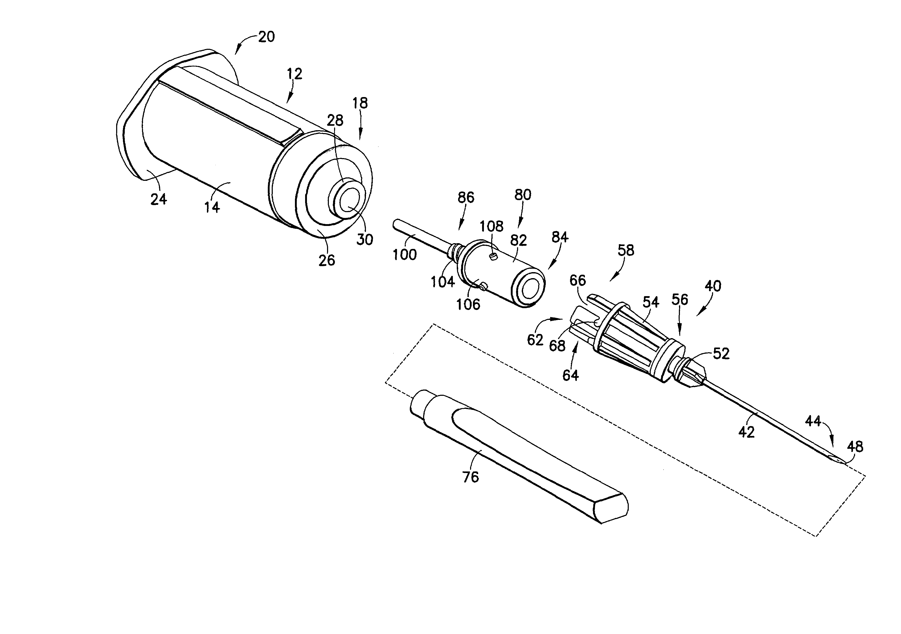
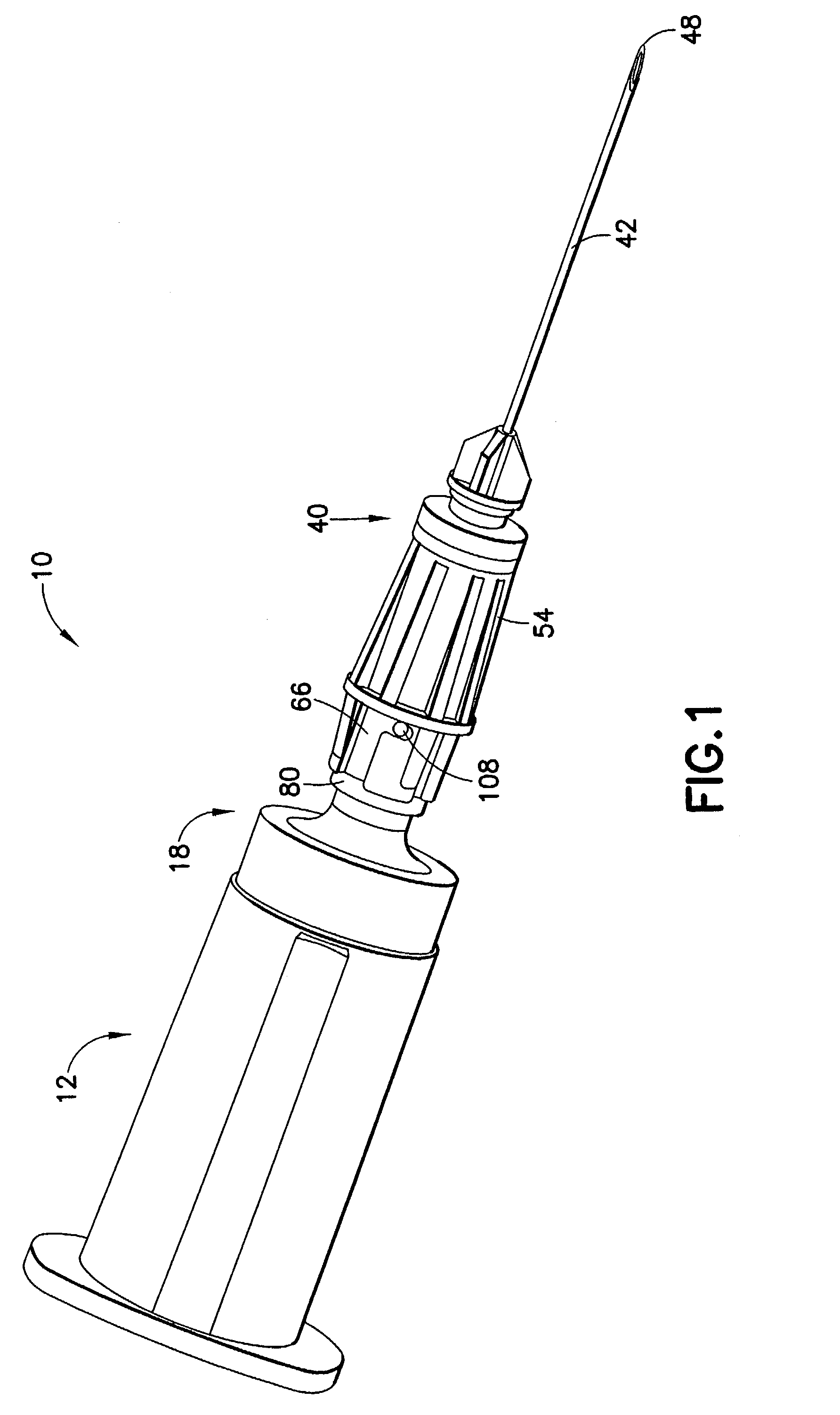
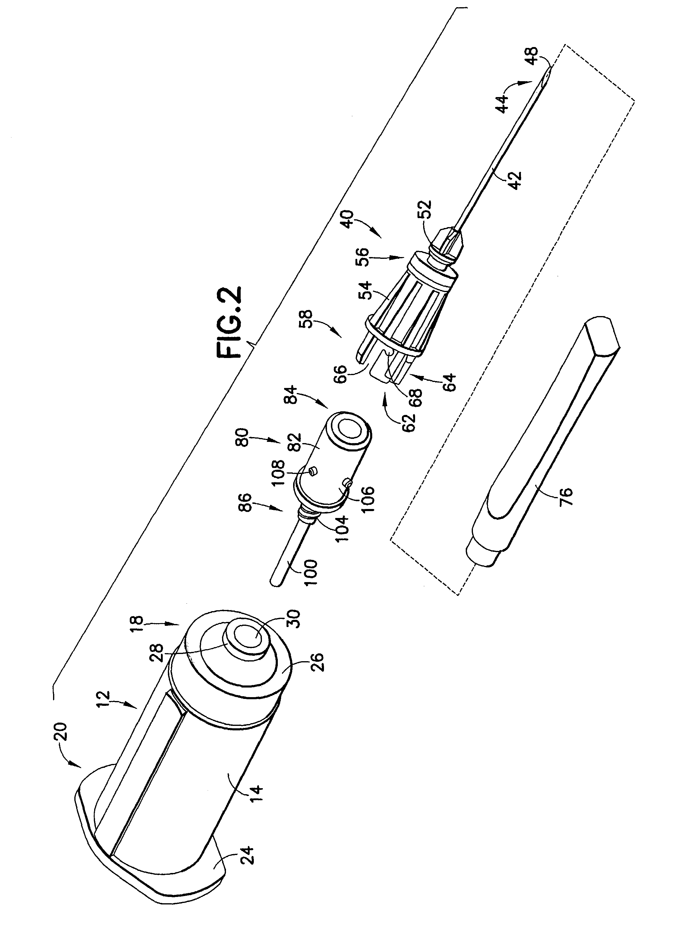
[0022]Referring to the drawings in which like reference characters refer to like parts throughout the several views thereof, FIG. 1 illustrates a collection assembly including a needle holder and an intravenous needle assembly connected through a coupler, in accordance with the present invention and the related features. The present invention is generally descri...


PUM


Abstract

The present invention is directed to a coupler for providing fluid connection between a needle holder and an intravenous needle assembly. The coupler includes a coupler housing and a coupler needle cannula. The coupler housing includes a forward end and a rearward end with the forward end having a piercable septum. The coupler housing also includes at least one lug on its external surface. The coupler is capable of forming a blood collection assembly to provide for fluid connection between a conventional needle holder and an intravenous needle assembly which includes guide slots traditionally provided for engagement with lugs on specific specimen tube arrangements.

Description

BACKGROUND OF THE INVENTION[0001]1. Field of the Invention[0002]The present invention relates to a blood collection assembly. More particularly, the present invention is directed to a coupler for connection of various needle and needle holder configurations.[0003]2. Description of Related Art[0004]Disposable medical devices having medical needles are used for administering medication or withdrawing fluid from the body of a patient. Such disposable medical devices typically include blood-collecting needles, fluid handling needles and assemblies thereof. Current medical practice requires that fluid containers and needle assemblies used in such devices be inexpensive and readily disposable. Consequently, existing blood collection devices typically employ some form of durable, reusable holder on which detachable and disposable medical needles and fluid collection tubes may be mounted. A blood collection device of this nature may be assembled prior to use and then disassembled after use....

Claims


Application Information

Patent Timeline
Patent Type & Authority Patents(United States)
IPC IPC(8): A61B5/00B65D81/00A61B5/15A61M5/34
CPCA61B5/1411A61M5/347A61M5/344A61B5/150587A61B5/15003A61B5/150259A61B5/150389A61B5/150496A61B5/150572A61B5/150717A61B5/150732A61B5/1545
Inventor MARSDEN, STEWART
Owner BECTON DICKINSON & CO
Learn More