
Method to improve planarity of electroplated copper

a technology of electroplated copper and planarity, applied in the field of integrated circuits, can solve the problems of high localization of blocking effects at the surface, complicated technology involved, and problems of type schematically

Inactive Publication Date: 2006-06-20
TAIWAN SEMICON MFG CO LTD
View PDF6 Cites 206 Cited by
  • Summary
  • Abstract
  • Description
  • Claims
  • Application Information

AI Technical Summary

Benefits of technology

The process effectively fills trenches of different widths, resulting in a uniform and planar metal layer across the substrate, addressing the issue of uneven deposition and achieving optimal filling of both narrow and wide trenches.

Problems solved by technology

The technology involved is further complicated by the fact that the effects of these multiple additives are often interactive.
However, they are present in very small concentrations (<25 ppm) so their blocking effects at the surface are highly localized.
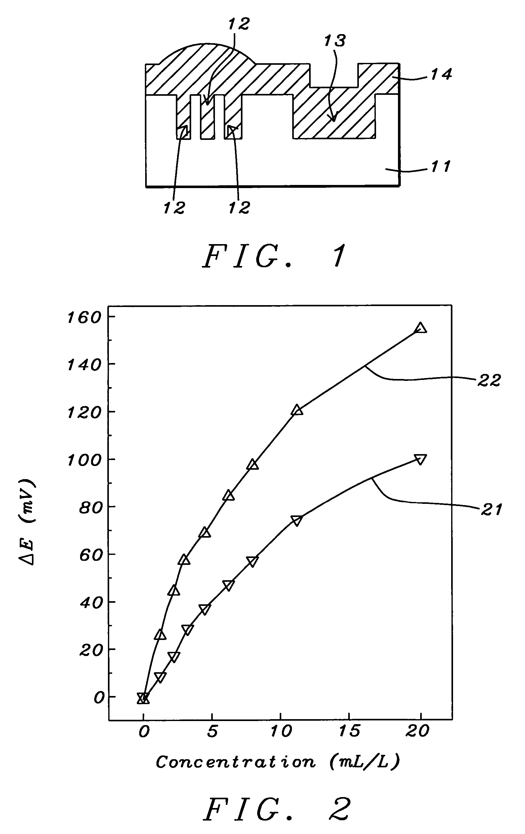
This results in problems of the type schematically illustrated in FIG. 1.

Method used


Image

  • Method to improve planarity of electroplated copper
  • Method to improve planarity of electroplated copper
  • Method to improve planarity of electroplated copper

Examples


Embodiment Construction

[0020]Some examples of accelerators are 3-sulfopropyldisulfide, 41 sulfonated acetylthiourea, 3-mercapto-1-propanesulfonate (MPSA), and dibenzyl-dithio-carbamate.

[0021]The precise concentration of accelerator additive that is needed to produce a given deposition rate can vary from one additive to another. We illustrate this in FIG. 2 which compares the effects of two different chemicals when added to a plating bath as an accelerator. Curves 21 and 22 are plots of ‘potential difference needed to initiate plating’ (which equates with film growth rate) vs. additive concentration in parts per thousand. Thus, although both curves are similar in form, the chemical associated with curve 21 is less effective than the one associated with curve 22. Examples of the former include 3-sulfopropyldisulfide, while examples of the latter include 3-mercapto-1-propanesulfonate (MPSA).

[0022]The process of the present invention begins with the provision of silicon wafer 11 (as seen for example in FIG. 1...


PUM

PropertyMeasurementUnit
widthaaaaaaaaaa
widthaaaaaaaaaa
thicknessaaaaaaaaaa

Abstract

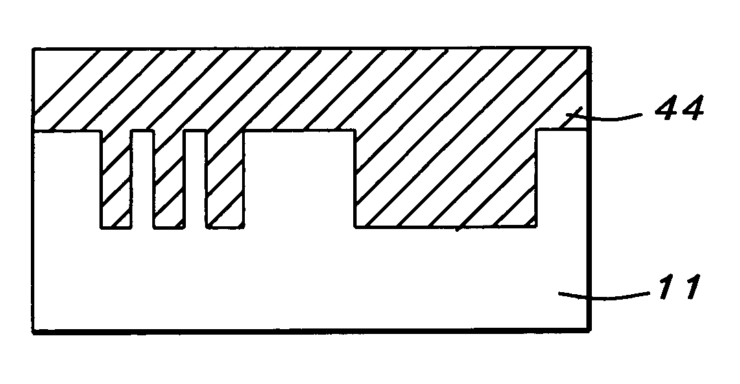
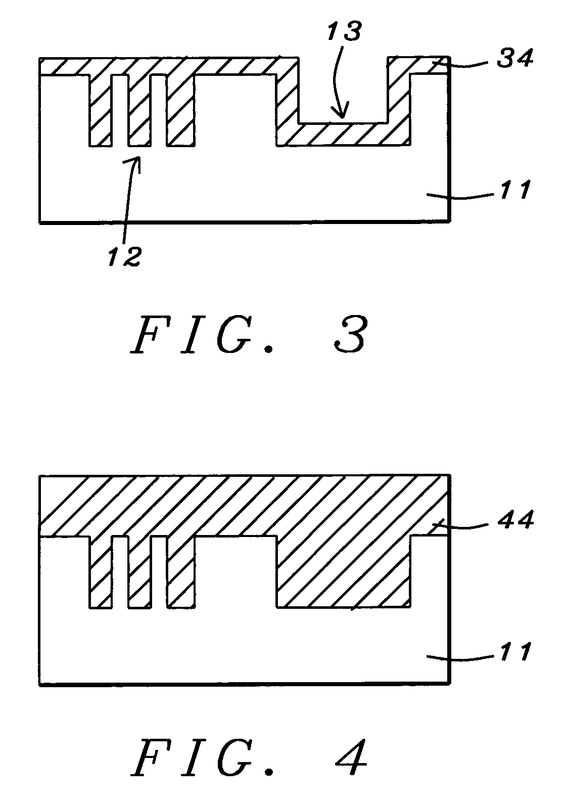
Narrow trenches in a substrate tend to fill more rapidly than wide trenches This results in a non-planar surface once all trenches have been filled. The present invention solves this problem by performing the electro-deposition in two steps. The plating bath used during the first step, is optimized for filling narrow trenches while the plating bath used during the second step, is optimized for filling wide trenches. The net result is a final layer having a planar surface, with all trenches being properly filled.

Description

FIELD OF THE INVENTION[0001]The invention relates to the general field of integrated circuits with particular reference to filling trenches with metal.BACKGROUND OF THE INVENTION[0002]With the introduction of the damascene process, the formation of wires by filling trenches has become routine. Additionally, particularly for the case of copper-filled trenches, the method of choice for depositing the metal has been electroplating. However, as trenches have become narrower and narrower, it has become necessary to employ a range of additives that need to be included in the plating solution to give the best filling results. The technology involved is further complicated by the fact that the effects of these multiple additives are often interactive.[0003]We can identify three broad additive types:[0004]Accelerators serve to increase the deposition rate during electroplating. They are usually small organic molecules containing a polar sulfur, oxygen, or nitrogen functional group. In additi...

Claims


Application Information

Patent Timeline
Patent Type & Authority Patents(United States)
IPC IPC(8): H01L21/44C25D3/38C25D5/10C25D7/12H01L21/288H01L21/4763H01L21/768H05K3/42
CPCC25D3/38C25D5/10H01L21/2885C25D7/123H01L21/76877H01L21/7684H05K3/423
Inventor CHOU, SHIH-WEITSAI, MING-HSINGLIN, MING-WEI
Owner TAIWAN SEMICON MFG CO LTD
Learn More