Self-ventilating disc brake rotor

a disc brake and self-ventilation technology, applied in the direction of brakes, braking elements, actuators, etc., can solve the problems of rotor disc swelling, cracking, stress fatigue,

Inactive Publication Date: 2006-06-27
DISC BRAKES AUSTRALIA
View PDF9 Cites 89 Cited by
  • Summary
  • Abstract
  • Description
  • Claims
  • Application Information

AI Technical Summary

Problems solved by technology

The result is a tendency to excessive temperature generation during severe br

Method used


Image

  • Self-ventilating disc brake rotor
  • Self-ventilating disc brake rotor
  • Self-ventilating disc brake rotor

Examples


first embodiment

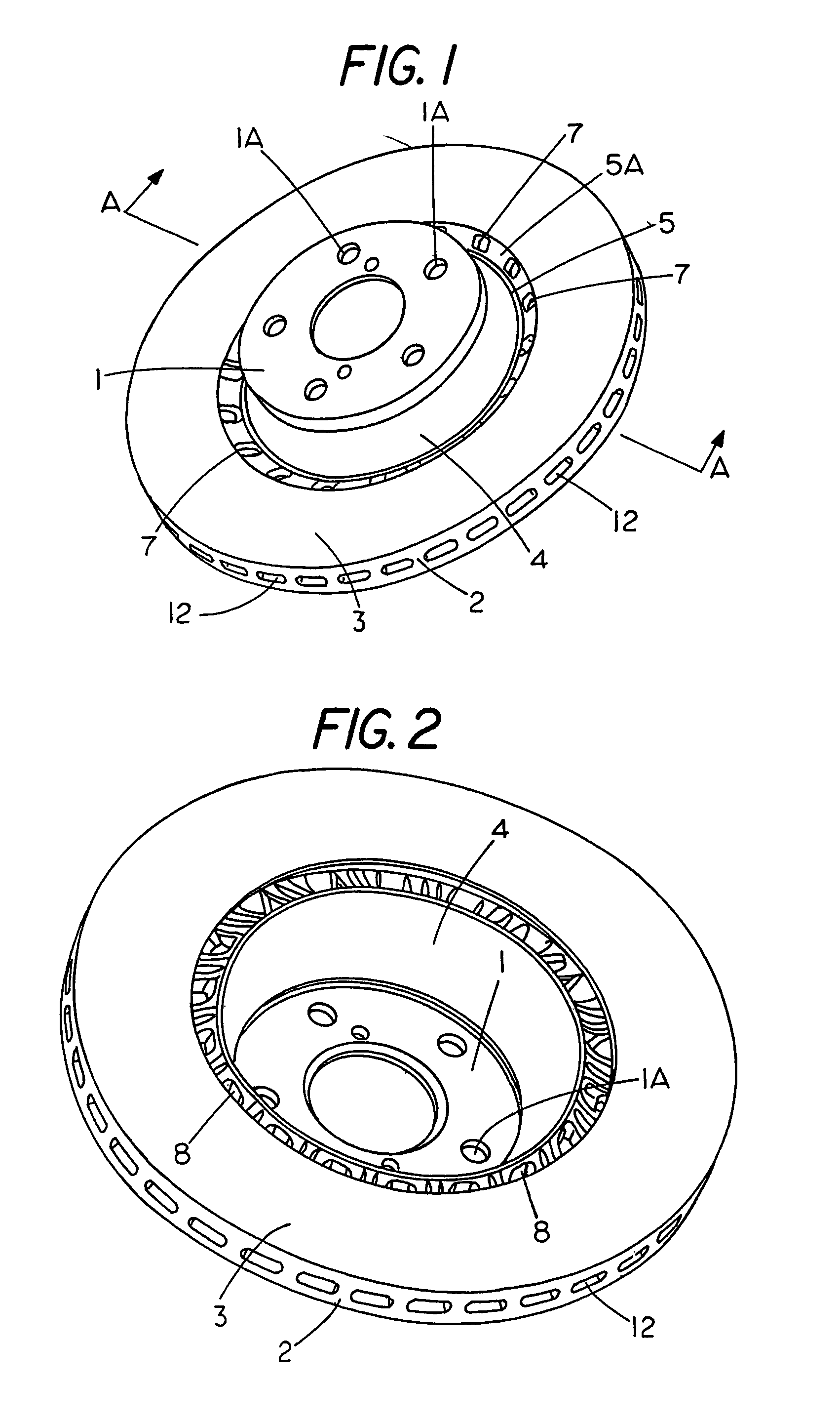
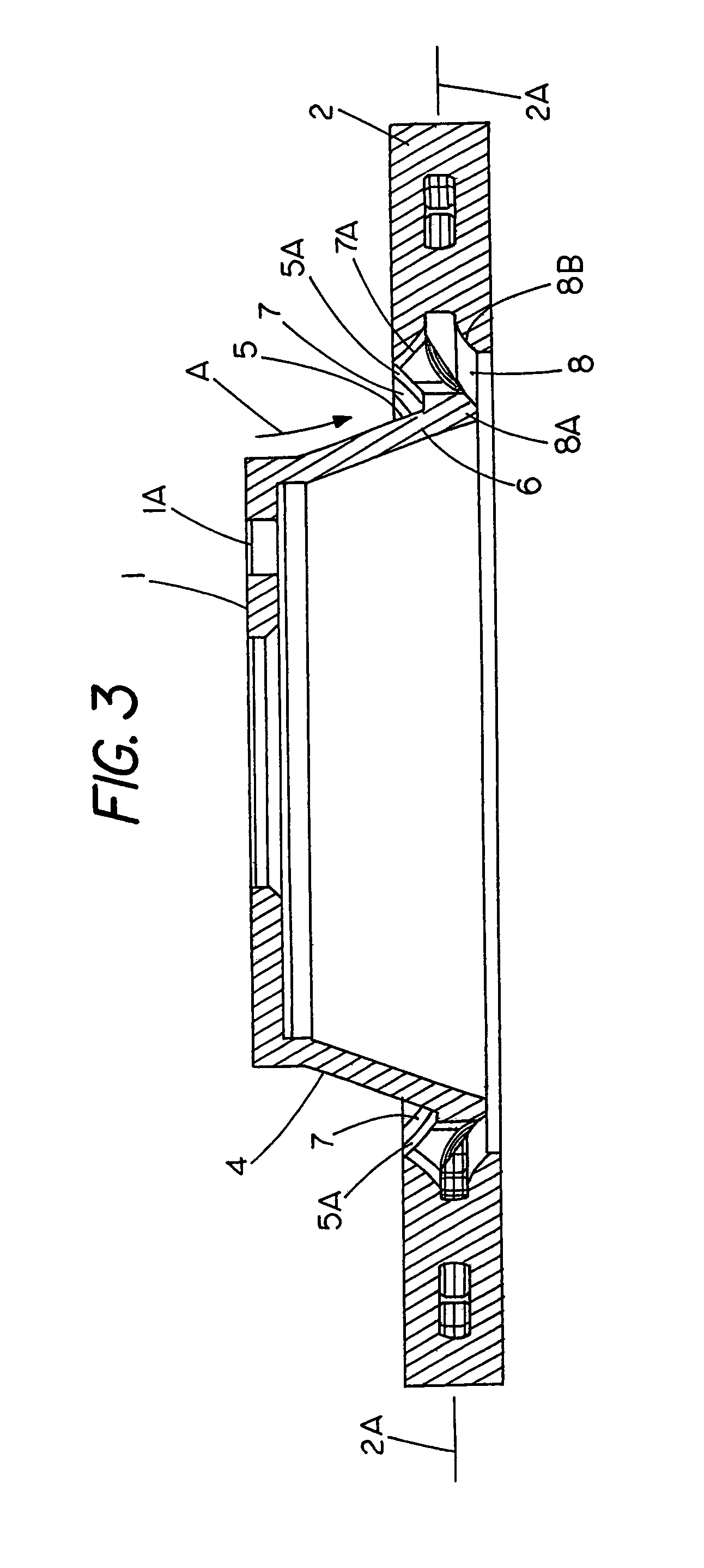
[0036]Referring first to FIGS. 1 to 3 there is a brake rotor comprising a central hub or hat 1 for mounting a vehicle wheel by means of bolts passing through apertures 1A. Surrounding the hat and co-axial with it are rings 2 which form brake bands 3 on the inboard and outboard sides for engagement with brake pads (not shown). The rings 2 are supported in a spaced apart parallel configuration by pillars with radial ventilation channels formed between them as described in more detail later. In accordance with a preferred embodiment of the invention the sides 4 of the hat or hub are inclined outwardly at about 4 degrees as best shown in FIG. 3. The outer periphery of the hat leads into a deep heat dam 5. This construction closely aligns the web 6 with the centre-line 2A of the rotor rings 2 to reduce vibration, better defines a heat distortion point for the rotor and also facilitates a smooth flow of air into the outboard vent ports 7. These ports 7 receive a flow of shown in FIG. 3. T...

second embodiment

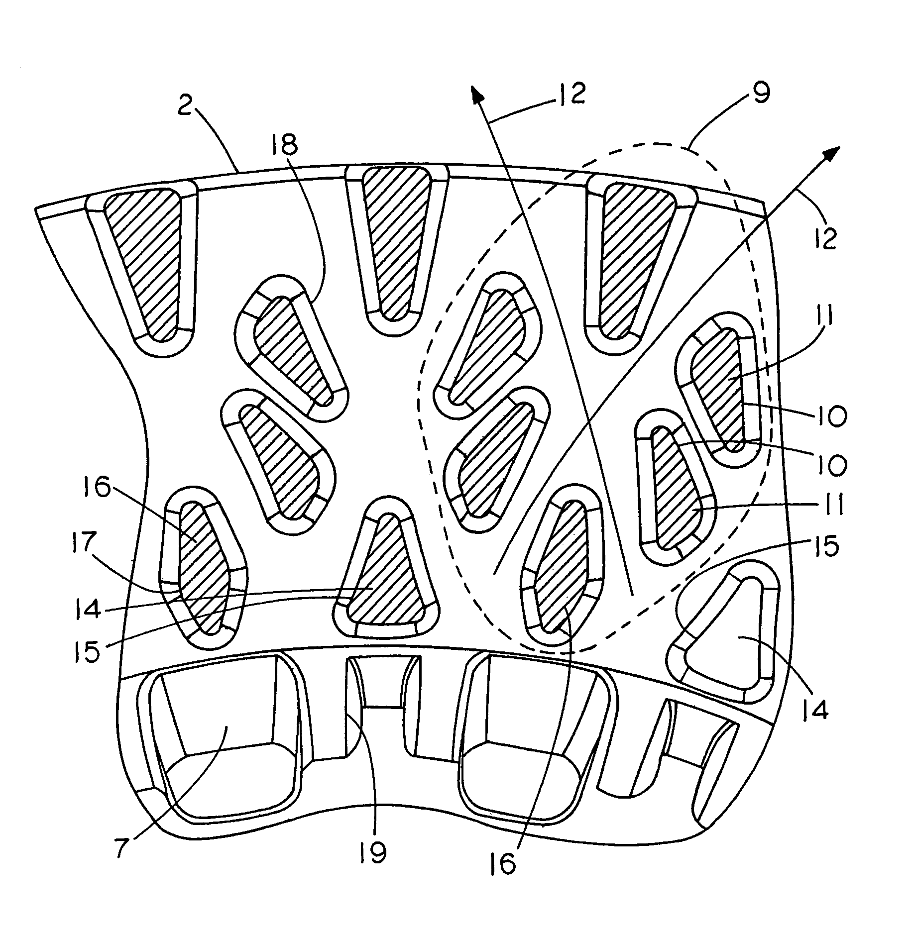
[0037]A preferred arrangement of the support pillars between the rings is shown in FIGS. 4 and 5. With this embodiment the pillars are disposed in repeating clusters of six units as indicated by broken line 9. Each cluster by means of the overlapping edges 10 and the elongated triangular shape of the pillars 11 defines radial air flow channels 12 out between the rings in accordance with the direction of rotation. There are also inner pillars 14 which are preferably triangular or bell shaped in cross-section so that the curved edges 15 act as air scoops to draw air in through the vent ports 8 and 9. Alternating with these pillars 14 are elongated diamond shaped pillars 16 which are asymmetrical in the radial direction so that the widest point 17 is offset toward the centre of the rotor. This shape has been found to better deflect and draw the air from the vent ports into the channels.

[0038]As the layout of each pillar cluster is preferably symmetrical with respect to the two opposite...


PUM


Abstract

There is a brake disc rotor having a central hub (1) co-axial with surrounding rings (2) which form brake bands (3) for engagement with brake pads. The rings (3) are supported in a spaced apart parallel configuration with channels (12) therebetween whereby in use of the rotor cooling air is drawn in through vent openings formed around the inner periphery of the rings (3) and then radially outwardly through the channels (12) as the rotor turns. The vent openings include inlet vent ports (7) on the outboard side of the rotor.

Description

[0001]This application is a continuation-in-part application of application Ser. No. 10 / 459,766, filed Jun. 12, 2003 now abandoned, which is a continuation-in-part application of application Ser. No. 09 / 888,942, filed Jul. 25, 2001, now abandoned.FIELD OF THE INVENTION[0002]This invention relates to brake apparatus. More particularly although not exclusively it discloses an improved rotor for vehicle disc brakes.BACKGROUND OF THE INVENTION[0003]Existing disc brake rotors typically comprise a central hub or hat co-axial with a surrounding ring and a brake band adapted for frictional contact with brake pads on each side. With self-ventilating disc brakes there are two spaced apart parallel rings and bands provided on each rotor which are cooled by a radial flow of air outwardly through channels formed between them. This flow largely results from centrifugal forces generated by rotation of the rotor.[0004]Prior art rotors have generally attempted to arrange pillars and other internal s...

Claims


Application Information

Patent Timeline
IPC IPC(8): F16D65/12F16D65/847
CPCF16D65/12F16D65/847F16D2250/0007F16D2065/1328
Inventor GAVIN, STEPHEN PATRICK
Owner DISC BRAKES AUSTRALIA
Why Eureka
Try Eureka