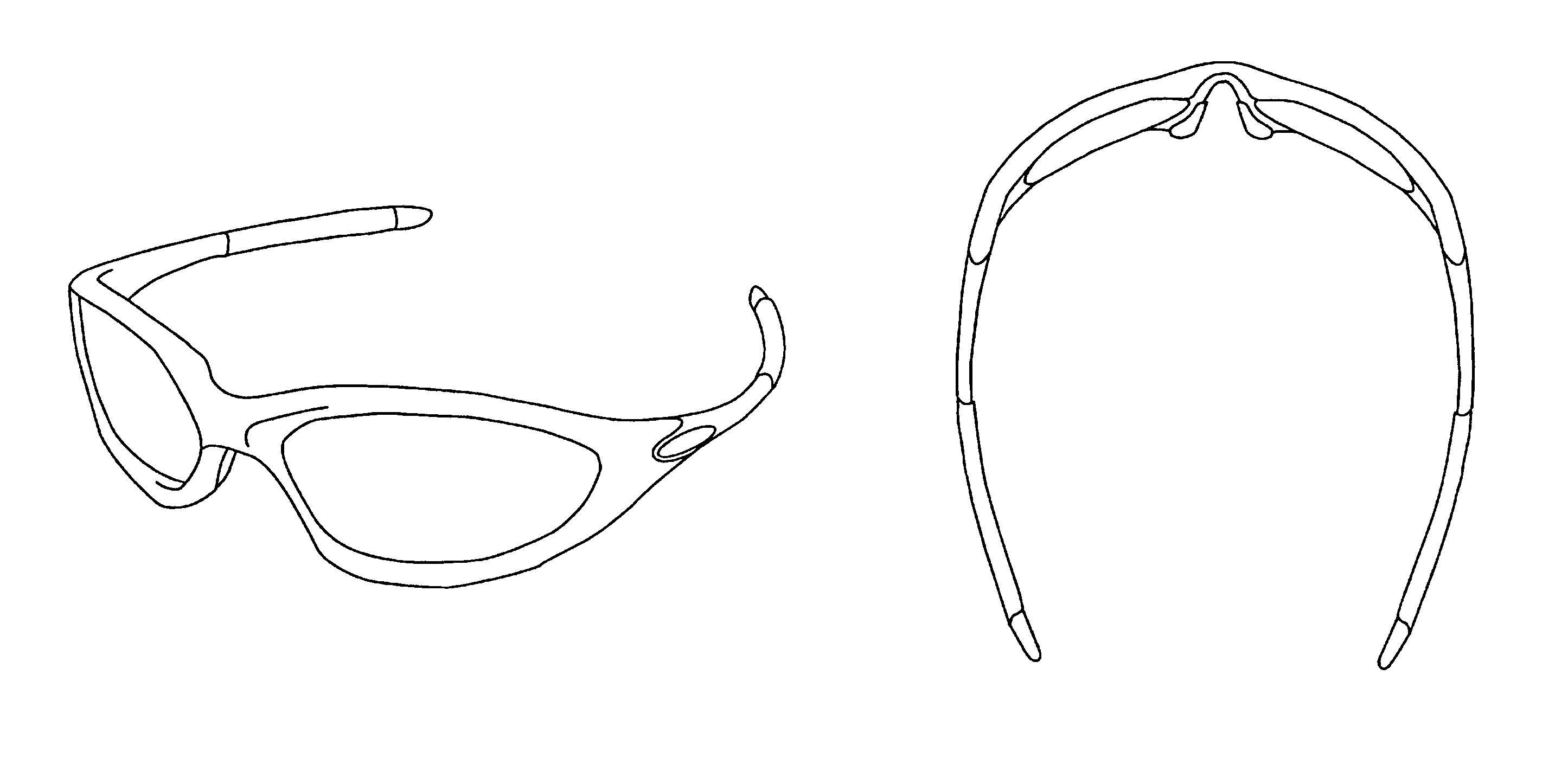
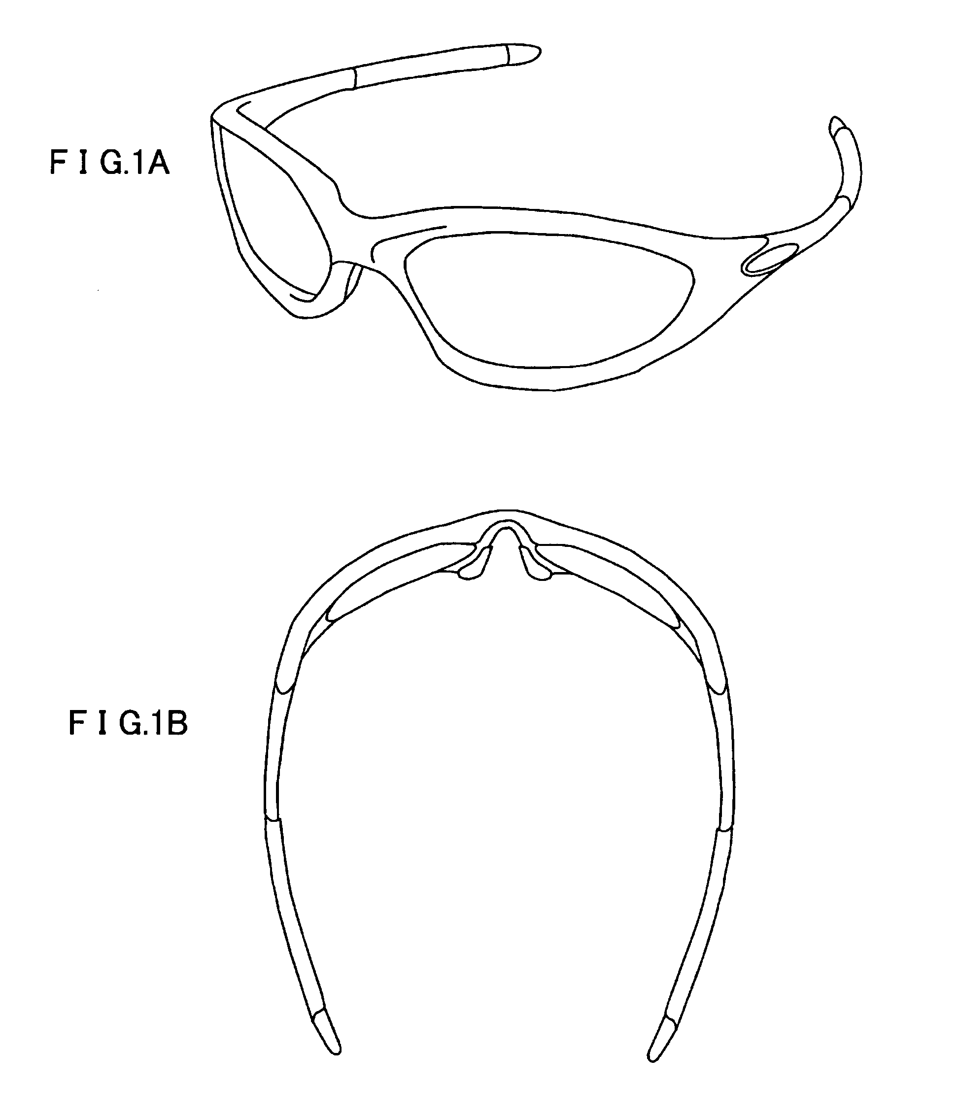
Spectacle lens

a technology of spectral lens and lens frame, applied in the field of spectral lens, can solve the problem of not having a spectacle lens optically corresponding to the wraparound type of spectacle frame, and achieve the effect of satisfying optical performan

Active Publication Date: 2006-07-04
HOYA LENS MFG PHILIPPINES
View PDF18 Cites 26 Cited by
  • Summary
  • Abstract
  • Description
  • Claims
  • Application Information

AI Technical Summary

Benefits of technology

[0008]The spectacle lens according to this embodiment is designed to be most suitable optically when the spectacle lens is mounted in a spectacle frame that has a camber angle of 200° or more and in which the spectacle lens inclines with respect to a line of sight. In other words, astigmatic aberration and prismatic effect are caused in the spectacle lens that is oblique in the horizontal direction with respect to the line of sight. Therefore, cylindrical power and prismatic power are added to the refractive surface on the object side or the refractive surface on the eye side to cancel out the astigmatic aberration and the prismatic effect at an arbitrary design reference point. Since the astigmatic aberration cannot be corrected in parts other than the design reference point simply by adding the cylindrical power and the prismatic power, the aspherical surfaces different from each other on the nose side and the ear side are formed, whereby it is possible to correct the astigmatic aberration of the entire spectacle lens satisfactorily and obtain a spectacle lens having satisfactory optical performance.
[0010]In a second embodiment, the invention provides a spectacle lens in which the spectacle frame has an angle of inclination, and the cylindrical power, for offsetting the astigmatic aberration caused by the angle of inclination, at the design reference point to the refractive surface on the object side or the refractive surface on the eye side, and prismatic power for offsetting prismatic effect, which is caused by the angle of inclination, at the design reference point is added to the refractive surface on the object side or the refractive surface on the eye side.
[0011]When a spectacle lens is mounted in a spectacle frame having a pantoscopic angle in addition to a camber angle, astigmatic aberration and prismatic effect are caused in the spectacle lens by the pantoscopic angle. Therefore, the cylindrical power and the prismatic power are added to the refractive surface on the object side or the refractive surface on the eye side to cancel out the astigmatic aberration and the prismatic effect at an arbitrary design reference point, whereby it is possible to obtain a spectacle lens having satisfactory optical performance.

Problems solved by technology

Conventionally, however, under the present situation, only an optical lens with a large curvature, corresponding to a deep curve of the wraparound type, is provided as a spectacle lens for correction that is mounted in the spectacle frame of the wraparound type, and no spectacle lens optically corresponding to the spectacle frame of the wraparound type has yet been provided.

Method used


Image

  • Spectacle lens
  • Spectacle lens
  • Spectacle lens

Examples


first embodiment

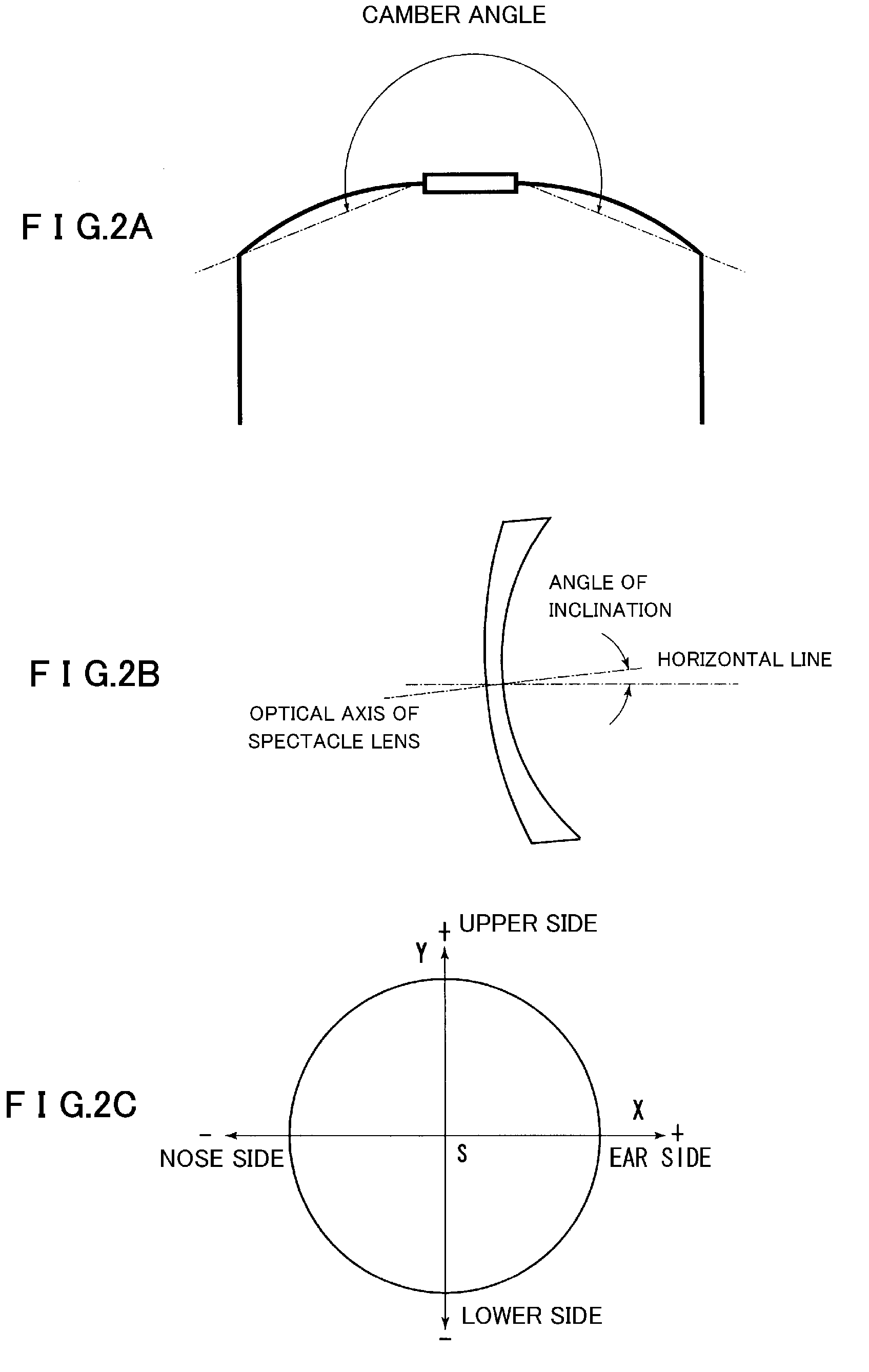
[0065]A single-vision lens of a spherical design, in which power of a refractive surface on an object side (a front surface) was 8 D (diopters), power of a refractive surface on an eye side (a back surface) was 10.54 D, a central thickness was 1.05 mm, dioptric power was −2.5 D, was used as a basic lens. It is assumed that this single-vision lens is mounted in a spectacle frame without a camber angle. FIG. 4(a) shows the astigmatic aberration at the time when this single-vision lens is mounted in the spectacle frame without a camber angle and FIG. 4(b) shows mean dioptric power. All figures to be described below shows the spectacle lens for the right eye. A horizontal line indicated by a broken line is the same as the X axis shown in FIG. 2(c) and a vertical line indicated by a broken line is the same as the Y axis shown in FIG. 2(c). An intersection in the centers of the horizontal line and the vertical line is a design reference point serving as an eye point. A left side of the ey...

second embodiment

[0073]As in the first embodiment, the following basic lens was used: a single-vision lens of a spherical design, in which the power of a refractive surface on an object side (a front surface) was 8 D (diopters), the power of a refractive surface on an eye side (a back surface) was 10.54 D, a central thickness was 1.05 mm, and the dioptric power was −2.5 D.

[0074]Correction of astigmatic aberration was applied to the refractive surface on the eye side assuming a case in which this lens was inclined around the eye point on the refractive surface on the object side and mounted in a spectacle frame of a wraparound type in which a camber angle was 210° and a pantoscopic angle was 8.66°. Here, the eye point on the refractive surface on the object side, around which the lens is inclined, is assumed to be an eye point and a design reference point at the time when the lens is mounted in the frame of the wraparound type astigmatic Aberration caused by a camber angle, prismatic effect caused by...


PUM


Abstract

To provide a spectacle lens that is designed optically to suit a spectacle frame with a large camber angle such as a wraparound type spectacle frame. A spectacle lens that is mounted in a spectacle frame with a camber angle of 200° or more, in which cylindrical power for offsetting astigmatic aberration, which is caused by the camber angle at a design reference point, is added to a refractive surface on an object side or a refractive surface on an eye side, prismatic power for offsetting prismatic effect, which is caused by the camber angle at the design reference point, is added to the refractive surface on the object side or the refractive surface on the eye side, and aspherical surfaces different from each other on a nose side and an ear side are formed on the refractive surface on the object side or the refractive surface on the eye side.

Description

[0001]This application claims the benefit of Japanese Application No. 2004-099224, filed Mar. 30, 2004, which is incorporated by reference, herein, in its entirety.FIELD OF THE INVENTION[0002]The present invention relates to a spectacle lens that is intended for use in a spectacle frame having a large camber angle, such as a wraparound type of frame.BACKGROUND OF THE INVENTION[0003]In recent years, a spectacle frame of the wraparound type has become popular, especially as sports sunglasses. An oblique perspective view of such a spectacle frame is shown in FIG. 1(a), and an upper side perspective view is shown in FIG. 1(b). As shown in FIG. 1, the spectacle frame of the wraparound type has a characteristic that, since the spectacle frame of the wraparound type has a large camber angle to bend around a face, even the sides of the face are covered by lenses and the field of view is wide. Therefore, a spectacle frame of the wraparound type (also known as “wraparounds”) is regularly used...

Claims


Application Information

Patent Timeline
Patent Type & Authority Patents(United States)
IPC IPC(8): G02C7/02
CPCG02C7/02G02C7/027
Inventor KAMISHITA, KAORUKATO, KAZUTOSHIKAGA, TADASHI
Owner HOYA LENS MFG PHILIPPINES
Why Eureka
Try Eureka