
Sliding cover

a technology of sliding cover and mobile phone, which is applied in the direction of electrical apparatus casing/cabinet/drawer, substation, instruments, etc., can solve the problems of dirt that could enter the interior of the device, the phone appears less rigid, and the space between the sliding cover and the mobile phone is difficult to clean,

Inactive Publication Date: 2006-07-04
INTELLECTUAL VENTURES I LLC
View PDF15 Cites 105 Cited by
  • Summary
  • Abstract
  • Description
  • Claims
  • Application Information

AI Technical Summary

Benefits of technology

[0015]Advantageously, a battery of the device can be placed on the bottom of the body such that it can be replaced after the first housing part is detached. This enables the user to easily swap the battery.
[0037]Advantageously, the snap-on attachment provides the user with a quick, intuitive and easy manner for exchanging the covers, including the sliding cover, and for cleaning the sliding cover.

Problems solved by technology

However, it the telephone falls, the sliding cover may meet an excessive force detaching it from the telephone or, in the worst case, breaking it.
Another drawback of the sliding cover that extends across an end of the telephone is that the telephone appears less rigid when the sliding cover is fully extended.
Furthermore, it may be troublesome to clean the space between the sliding cover and the mobile telephone should any dirt enter therein.
The solution is rather convenient for many uses, but it is yet susceptible to dirt that could enter the interior of the device as conveyed by the sliding cover.
When dirt accumulates on the backside space, the movement of the sliding cover becomes obstructed by the dirt.
It is therefore apparent that the construction would be somewhat laborious to assemble and serve.
Furthermore, such attachment is reasonably prone to mechanical damage when the first housing part is connected by a large portion of its sides.

Method used


Image

  • Sliding cover
  • Sliding cover
  • Sliding cover

Examples


Embodiment Construction

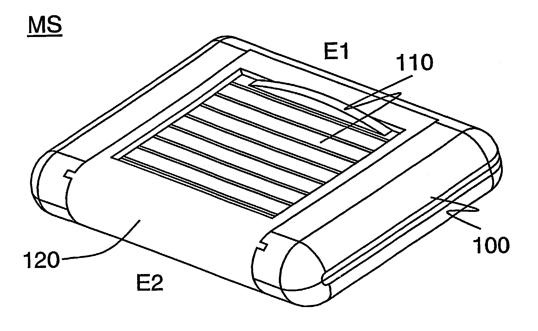
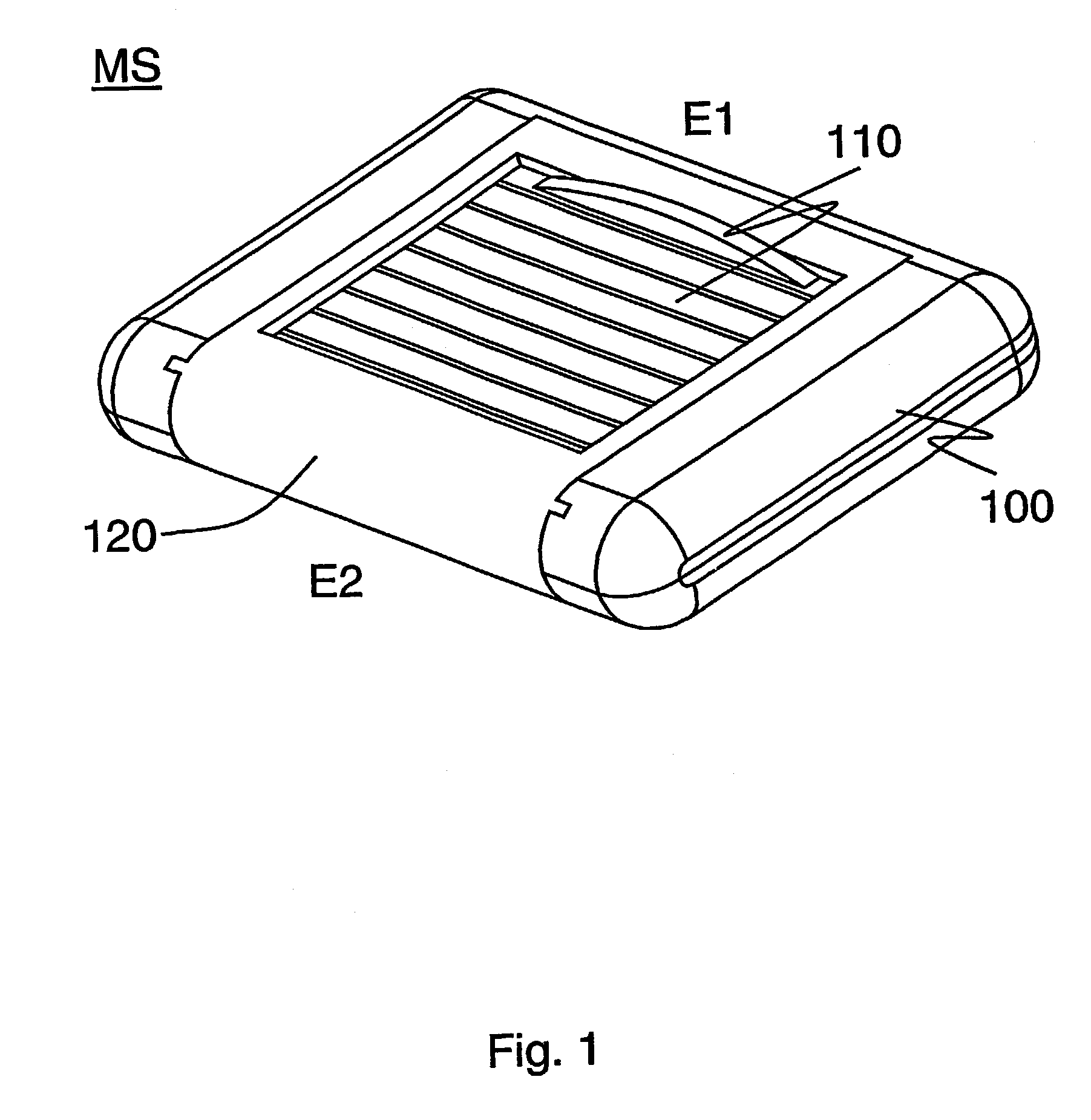
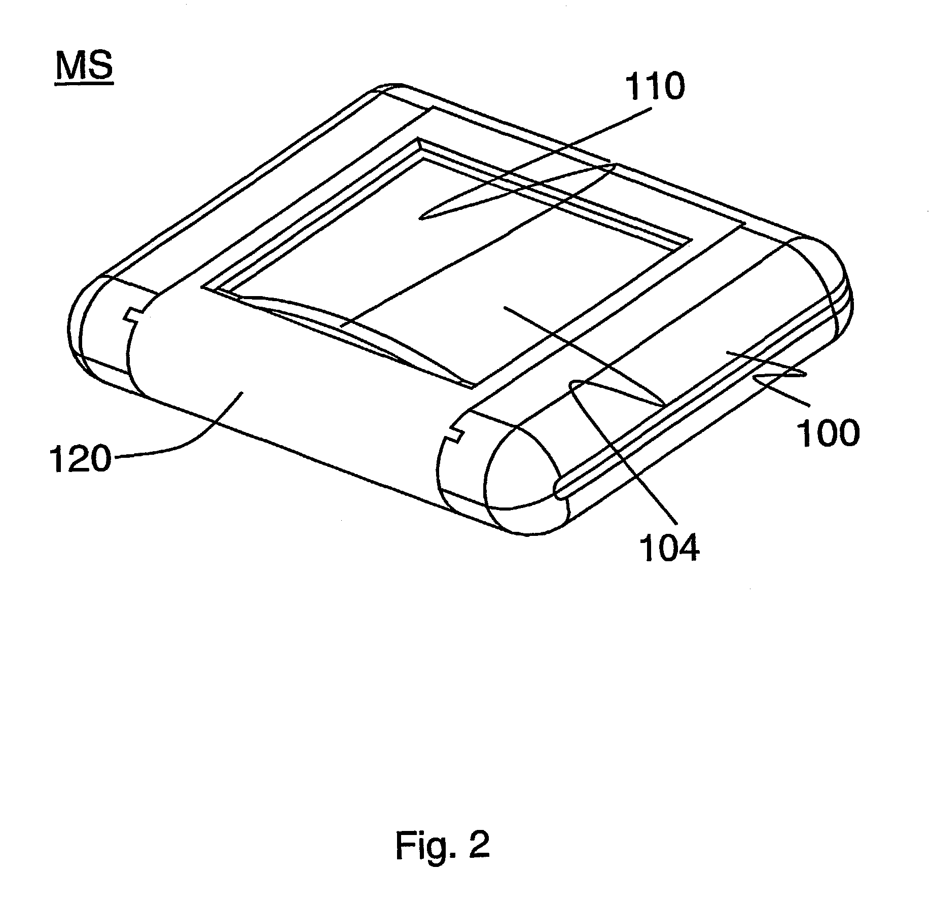
[0044]FIG. 1 shows, in a closed configuration, a mobile communications device MS according to a first embodiment of the invention. The figure shows parts of the mobile communications device MS essential to describe for understanding of the invention: a body 100, a sliding cover 110 and a rear cover 120. The body 100 has a relatively planar front plane of which a major part is covered by the sliding cover 110. The sliding cover 110 is surrounded and held in place by the rear cover 120, as is described in more detail below, with reference to FIGS. 3, 4a and 4b.

[0045]The mobile communications device MS shown in FIG. 1 is basically rectangular article with rounded edges and corners. It has a large, planar front and bottom surface (latter not shown) and rounded sides. The sides i.e. ends of the mobile communications device have following references: Front side S1 (FIGS. 4a, 4b),back side S2 (FIGS. 4a, 4b), a first end E1 and a second end E2 opposite to the first end E1. The thickness of...


PUM


Abstract

An electronic device with a body having a first side, a second side a distance from the first side, and a third side between the first and second side. Portions define a space extending from the first side to the second side across the third side. A sliding cover can be fitted in the space. A first housing part is detachably attachable to the electronic device and can cover at least part of the space when the housing part is attached to the electronic device. The first housing part can restrain the sliding cover from escaping the space when attached to the electronic device. The electronic device can allow, when the first housing part is detached from the electronic device, entry and removal of the sliding cover to and from the space. A cover system detachably attaches a sliding cover to an electronic device.

Description

[0001]This application is a continuation of international application number PCT / FI00 / 00851 filed Oct. 2, 2000, status pending.FIELD[0002]This invention relates to covers of devices. In particular, but not restricted to, the invention relates to sliding covers of mobile communications devices.BRIEF DESCRIPTION OF RELATED DEVELOPMENTS[0003]Various devices have been constructed with different flaps, sliding covers and clamp-shell type covers in order to protect or cover some elements contained by the device. For example, some mobile phones have a flap for protecting the keyboard when the keyboard is not needed. For accessing the keyboard, the flap is turned away. In sliding cover constructions, respectively a sliding cover protects the keyboard, when the keyboard is not used, and reveals the keyboard by sliding away when the keyboard is needed. The Nokia® 7110 GSM telephone is an example of the latter concept. There, the sliding cover also comprises a microphone that is brought closer...

Claims


Application Information

Patent Timeline
Patent Type & Authority Patents(United States)
IPC IPC(8): H04M1/00H04M1/02
CPCH04M1/0237H04M1/0254H04M2250/22
Inventor EIDEN, NIKO
Owner INTELLECTUAL VENTURES I LLC
Learn More