Intake device for engine

a technology for a fuel injection device and an engine, which is applied in the direction of combustion air/fuel-air treatment, machines/engines, mechanical equipment, etc., can solve the problems of air-fuel mixture, and achieve the effect of reducing harmful components in the exhaust gas and improving combustion efficiency

Active Publication Date: 2007-03-01
YAMAMOTO TOSHIHIKO
View PDF12 Cites 9 Cited by
  • Summary
  • Abstract
  • Description
  • Claims
  • Application Information

AI Technical Summary

Benefits of technology

[0006] The present invention has been made with the above circumstances in view and it is an object to provide an intake device for an engine, with which an atomization ratio of air-fuel mixture, combustion efficiency and fuel consumption can be improved and harmful components in exhaust gas can be reduced.

Problems solved by technology

However, straightening of the air-fuel mixture by using the straightening plate is not sufficient to atomize the air-fuel mixture and reduce harmful components in exhaust gas to ideal degrees.

Method used


Image

  • Intake device for engine
  • Intake device for engine
  • Intake device for engine

Examples


Embodiment Construction

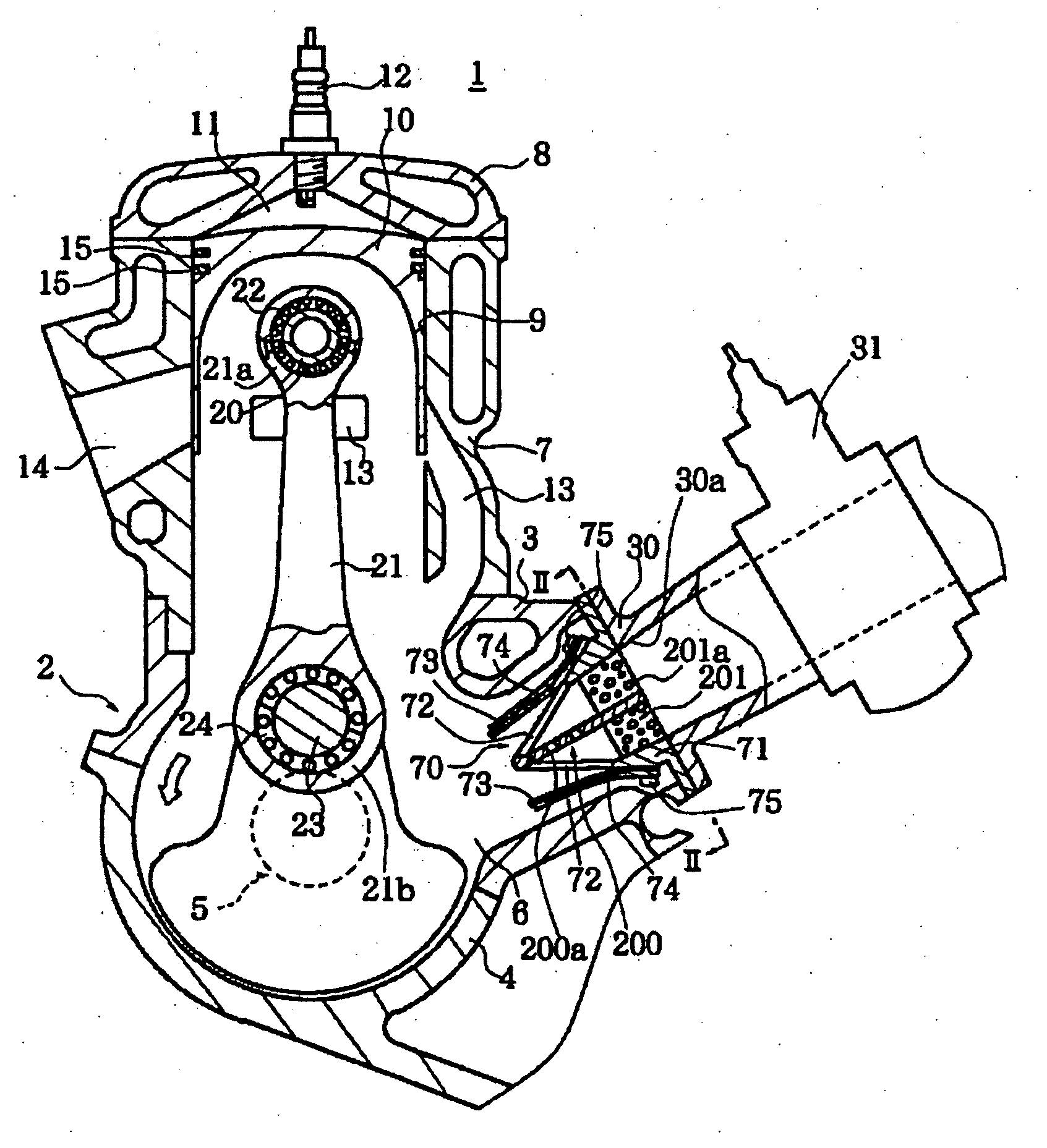
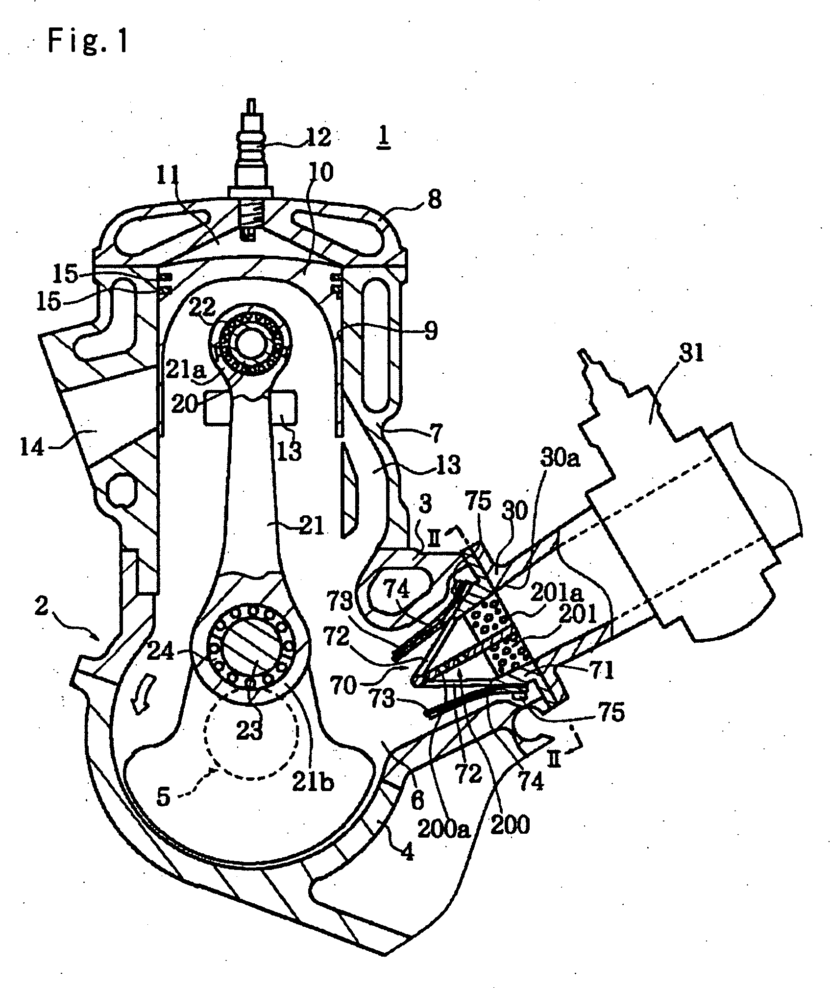
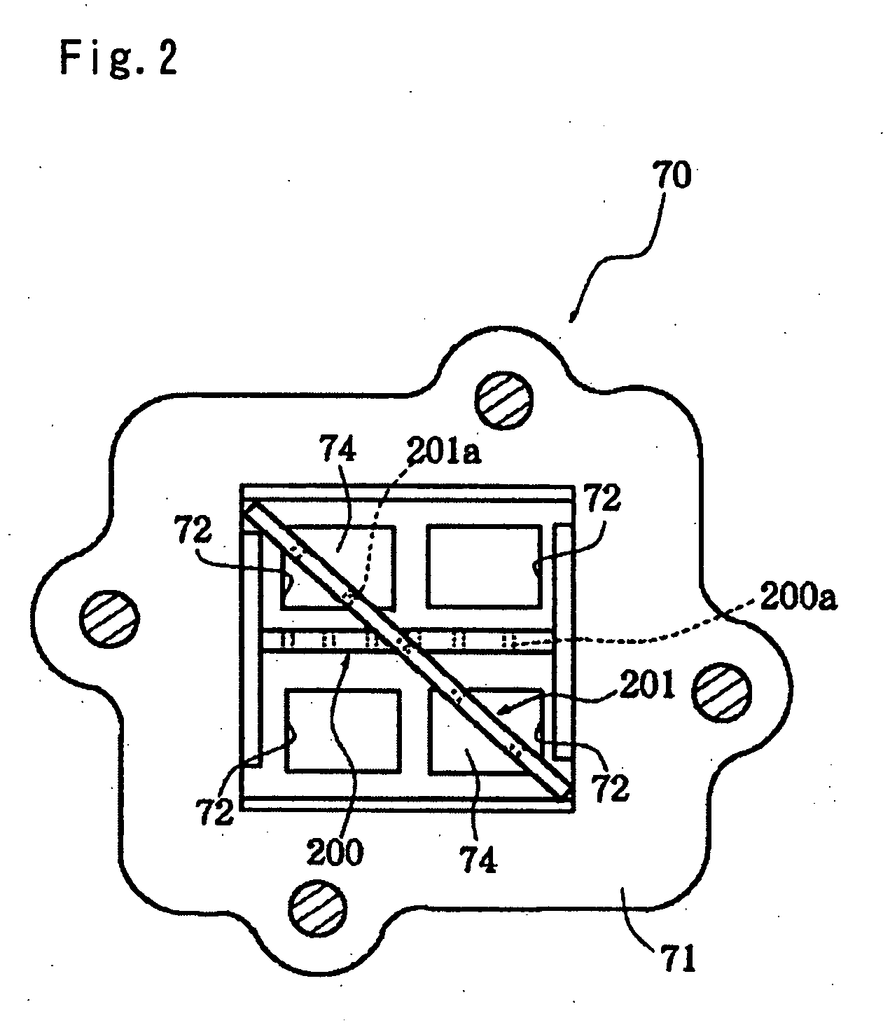
[0055] Embodiments of an intake device for an engine according to the invention will be described below based on the drawings. FIGS. 1 to 3 show the embodiment applied to a two-cycle engine. FIG. 1 is a vertical sectional view of the two-cycle engine having the intake device. FIG. 2 is a sectional view taken along a line II-II of the backside in FIG. 1. FIG. 3 is a drawing showing another arrangement of a plate having a large number of holes.

[0056] This two-cycle engine 1 includes a crankcase 2 composed of an upper case 3 and a lower case 4. Between the upper case 3 and the lower case 4, a crankshaft 5 is axially supported to be rotatable. The upper case 3 and the lower case 4 form a crank chamber 6.

[0057] A cylinder block 7 is mounted to the upper case 3 and a cylinder head 8 is mounted to the cylinder block 7. In a cylinder 9 formed in the cylinder block 7, a piston 10 is provided to be able to reciprocate. Among the cylinder 9, a head of the piston 10, and the cylinder head 8, ...


PUM


Abstract

In an intake device for an engine, the device having a fuel supply system for supplying fuel to an intake passage, a plurality of plates are positioned on an upstream side and a downstream side along a direction of a flow of intake air and arranged at different mounting angles from each other in the intake passage on a downstream side of the fuel supply system and the plurality of plates have a plurality of holes in different shapes.

Description

BACKGROUND OF THE INVENTION [0001] (1) Field of the Invention [0002] The present invention relates to an intake device for an engine including a fuel supply system for supplying fuel to an intake passage. [0003] (2) Description of Prior Art [0004] Conventionally, there is a two-cycle engine or a four-cycle engine as an engine mounted on a vehicle such as a two-wheeled motorcycle and each of these engines is provided with an intake device. Some intake devices include fuel supply systems for supplying fuel to intake passages. [0005] A mixture of air and fuel is supplied to such an intake device. Some intake devices include straightening plates disposed in intake passages in order to improve filling efficiency of the air-fuel mixture. However, straightening of the air-fuel mixture by using the straightening plate is not sufficient to atomize the air-fuel mixture and reduce harmful components in exhaust gas to ideal degrees. SUMMARY OF THE INVENTION [0006] The present invention has been...

Claims


Application Information

Patent Timeline
Patent Type & Authority Applications(United States)
IPC IPC(8): F02M29/04F02B33/04
CPCF01L3/205F01L2001/0537F02M29/04F02M35/1019Y02T10/14Y02T10/12
Inventor YAMAMOTO, TOSHIHIKO
Owner YAMAMOTO TOSHIHIKO
Why Eureka
Try Eureka