Device and method for setting a frame

Inactive Publication Date: 2006-07-11
PISCOVICH JOHN
View PDF17 Cites 4 Cited by
  • Summary
  • Abstract
  • Description
  • Claims
  • Application Information

AI Technical Summary

Benefits of technology

[0015]One or more embodiments of the present invention may achieve, but do not necessarily achieve, one or more of the following advantages:
[0016]allow utility container frames to be set using minimum components;
[0017]allow utility container frames to be quickly and easily set;
[0018]allow utility cont

Problems solved by technology

The concrete may substantially interfere with the function of container 14, such as providing a space to hold equipment or channeling runoff to a storm drain system.
Thus, the prior art method requires a lot of clean-up time and effort.

Method used


Image

  • Device and method for setting a frame
  • Device and method for setting a frame
  • Device and method for setting a frame

Examples


Embodiment Construction

[0044]In the following detailed description of the preferred embodiments, reference is made to the accompanying drawings, which form a part of this application. The drawings show, by way of illustration, specific embodiments in which the invention may be practiced. It is to be understood that other embodiments may be utilized and structural changes may be made without departing from the scope of the present invention.

Prior Art

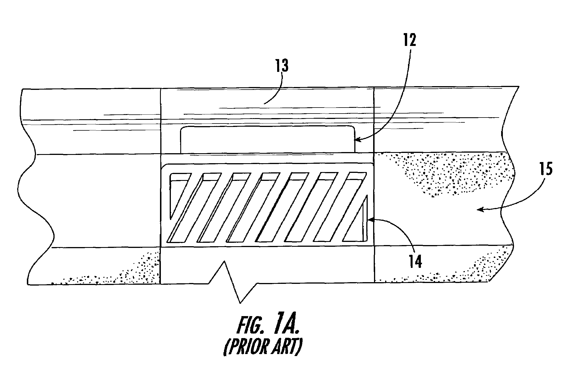
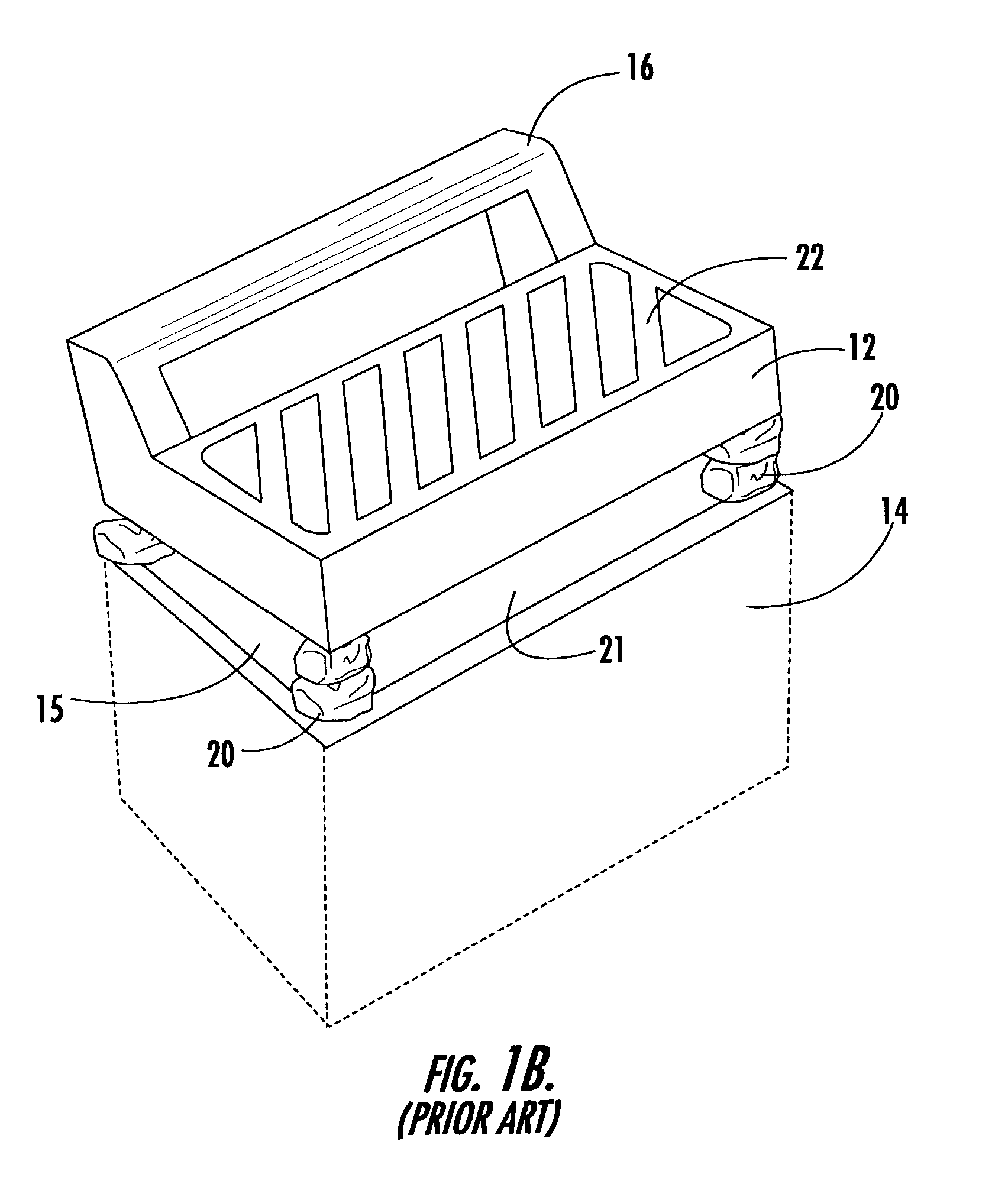
[0045]FIGS. 1A and 1B shows a prior art method of setting a frame 12 over a utility container 14 to create a curb 13 and gutter 15. Container 14 is placed in a hole in the ground a predetermined depth below the pavement surface. A top opening is formed by the walls of container 14 for providing access to the interior of the container from the top. Other openings (not shown) may be provided in the container for providing access to utility lines, such as pipes or conduits. Frame 12 is set on top of utility container 14. In most cases, frame 12 is set so that its ...


PUM


Abstract

The present invention comprises an apparatus for supporting a frame from a utility container. The apparatus comprises a plurality of support members being configured to form a box. The support members are slidably attached to each other. The apparatus further comprises at least one actuator being positioned between and attached to the support members. When the actuator is caused to lengthen, the support members slide away from each other until the box maintains position in the utility container thereby providing support to the frame.

Description

FIELD OF INVENTION[0001]The present invention relates to a method and apparatus for setting utility container frames in concrete.BACKGROUND[0002]Most streets, parking lots, and other paved surfaces have utility containers placed underneath them for housing or providing access to various utilities, such as storm drains, gas lines, telephone lines, sewer lines, cable television lines, power lines, etc. Each utility container generally has a frame that defines an opening for providing access to the container. In general, the frame is positioned so that it is a predetermined orientation to the paved surface. For example, it is often desirable for the frame to be positioned so that it is substantially flush with the paved surface.[0003]As an example, many paved surfaces have gutters to catch and carry off runoff fluids, such as rainwater. Gutters generally channel runoff to catch basins that are placed underneath the gutters. The catch basins collect the runoff and channel it to a storm ...

Claims


Application Information

Patent Timeline
IPC IPC(8): E04G17/00E01C7/00E01C23/01E03F5/04
CPCE01C23/01E03F5/0401E03F5/0408Y10S248/913E03F2005/0413E03F2005/0415
Inventor PISCOVICH, JOHN
Owner PISCOVICH JOHN
Why Eureka
Try Eureka