Automatic welding machine

a welding machine and automatic technology, applied in the field of automatic welding machines, can solve the problems of cumbersome and time-consuming handling, and achieve the effect of simplifying the operation of the automatic welding machine and extending the heating devi

Active Publication Date: 2018-03-27
LEISTER TECHNOLOGIES
View PDF17 Cites 4 Cited by
  • Summary
  • Abstract
  • Description
  • Claims
  • Application Information

AI Technical Summary

Benefits of technology

[0009]In a preferred embodiment of the tensioning device, a replacement of the spring-loaded element is provided. The spring-loaded element is disposed easily accessibly on the tensioning device and can be removed in just a few steps, for example by unscrewing a nut and pulling out the spring-loaded element. A different spring-loaded element can be inserted just as quickly and easily. Instead of replacing the spring-loaded element, this may also be preloaded so as to operate in a different spring characteristic curve range. The preload can be quickly and easily set, for example by way of a nut. Providing both options for setting the tension force in a tensioning device is an obvious choice.
[0019]The tensioning device allowing one-handed operation by way of the actuating lever thus moves the opposing pressing and advancing rollers to the plastic films, applies the necessary pressing pressure, and prompts the potentially present heating device to be extended. The combination of these steps simplifies the operation of the automatic welding machine.

Problems solved by technology

The individual functions are usually divided into individual steps from mechanical and control points of view; however, this makes handling more cumbersome and time-consuming.

Method used


Image

  • Automatic welding machine
  • Automatic welding machine
  • Automatic welding machine

Examples


Embodiment Construction

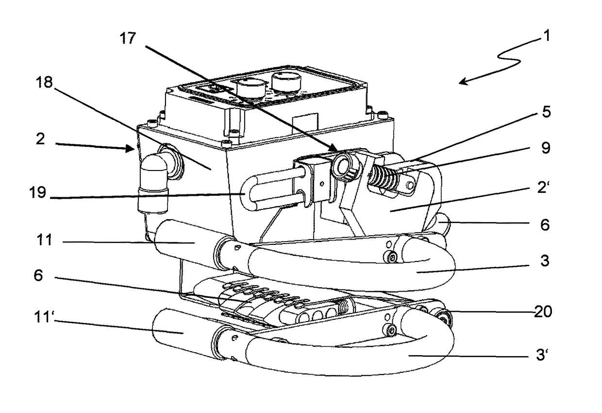
[0029]FIG. 1 shows an automatic welding machine 1 according to the invention for fusing plastic webs, which are not shown in the drawing. The shown automatic welding machine is an exemplary embodiment, in which the pressing and advancing rollers 11 and 11′ are each driven by way of a flexible shaft, which is not shown. A supporting frame 2 of the automatic welding machine 1 is displaceably supported on drive rollers 20. By way of example, the supporting frame 2 comprises a housing 18, which houses a driving device, which is not shown in the drawing, comprising a drive motor and at least one gearbox. A pillow block, which is not visible and forms part of the supporting frame 2, is also fastened to the housing 18 or the supporting frame 2 and the tensioning device 17 is mounted and fixed thereon. A supporting element 2′, which in the present exemplary embodiment is fastened to the housing 18, on the sides of which in turn two booms 3, 3′ are disposed, forms part of the tensioning devi...


PUM

PropertyMeasurementUnit
tension forceaaaaaaaaaa
torqueaaaaaaaaaa
spring forceaaaaaaaaaa

Abstract

An automatic welding machine, comprising a supporting frame and a tensioning device for reversibly joining at least two opposing booms to one another and applying a tension force between these, having an open position in which the opposing booms are separated from one another by a gap and a closed position in which the opposing booms are joined to one another and braced with respect to one another. One boom is mounted in a torsion-proof manner on the tensioning device and is pivotable in relation to the other boom and can be moved out of the open position into the closed position by the pivoting of the tensioning device. The tension force is generated by way of a spring-loaded element disposed on the tensioning device, wherein the spring-loaded element, at one end, is rigidly connected to a supporting element of the tensioning device and, at the other end, is pivotably mounted on the supporting frame by way of a double swivel joint, and the spring-loaded element is tensioned by the pivoting of the double swivel joint out of the open position into the closed position, whereby a torque is applied onto the pivotable boom.

Description

CROSS-REFERENCE TO RELATED APPLICATION[0001]The present application claims priority under 35 USC § 119 to European Patent Application No. 16 156 235.0 filed on Feb. 18, 2016, the entire disclosure of which is incorporated herein by reference.TECHNICAL FIELD[0002]The invention relates to an automatic welding machine for fusing plastic webs, comprising a movable supporting frame, a heating device for partially melting the plastic webs, at least two opposing booms comprising pressing and advancing rollers, at least one driving device, and a tensioning device that is mounted on the supporting frame and comprises an actuating element for reversibly joining the booms and applying a tension force between these, having an open position in which the opposing booms are separated by a gap and a closed position in which the opposing booms are joined to one another and braced with respect to one another, wherein one boom is mounted pivotably in relation to the other boom and brought from the ope...

Claims


Application Information

Patent Timeline
Patent Type & Authority Patents(United States)
IPC IPC(8): B29C65/00B29C65/02B29C65/20B29L7/00
CPCB29C65/02B29C66/81B29C65/20B29C66/814B29C66/8161Y10T156/18B29C66/8221B29C66/8362B29C66/86523B29L2007/008B29C66/82B29C65/18B29C66/45B29C66/80B29C65/103B29C65/2061B29C65/72B29C66/1122B29C66/232B29C66/43B29C66/81417B29C66/81422B29C66/8227B29C66/872
Inventor NIEDERBERGER, ADOLFFREI, MATHIASVON WYL, BRUNO
Owner LEISTER TECHNOLOGIES
Why Eureka
Try Eureka