Step and rafter tool

a tool and step technology, applied in the field of step and rafter tools, can solve the problems of easy loosening of setting, thin adjustable sliding scale, and lack of generous surface area of the levy, and achieve the effect of quick movement and use of the tool, and convenient us

Inactive Publication Date: 2012-02-28
FARR HARVEY H +1
View PDF27 Cites 10 Cited by
  • Summary
  • Abstract
  • Description
  • Claims
  • Application Information

AI Technical Summary

Benefits of technology

[0014]It is an object of the present invention is to provide a step and rafter tool comprising cooperative members which can be quickly and easily set to a predetermined position relative to one another, that position being clearly indicated by lines and indicia engraved within the members.
[0015]Another object of the present invention is to provide a step and rafter tool which can be set once for a given pitch for a particular stringer or roof rafter and then be used to mark all those steps or rafters without the need of subsequent changes in the tool setting.
[0017]Another object of the present invention is to provide a step and rafter tool which contains an easy to use reference tables which make calculation of rafter lengths for various situations such as hip, hip jack or common roof rafters easy.
[0018]Another object of the present invention is to provide a step and rafter tool which has two generous surfaces to slide on both the front face and the narrow side of the board at the same time to make movement and use of the tool quick and easy.

Problems solved by technology

Further, Levy doesn't provide a side bracket with a generous surface area, but instead has narrow ruler edges which can easily slide off the edge of the board.
However, the framing square is not slotted to receive the bolts and would therefore easily loose it's setting.
Further, the adjustable sliding scale is thin and will slide off the edge of the board during use.
However, Marty lacks any marks, indicia or reference tables to set the tool for rafter line marking.

Method used


Image

  • Step and rafter tool
  • Step and rafter tool
  • Step and rafter tool

Examples


Embodiment Construction

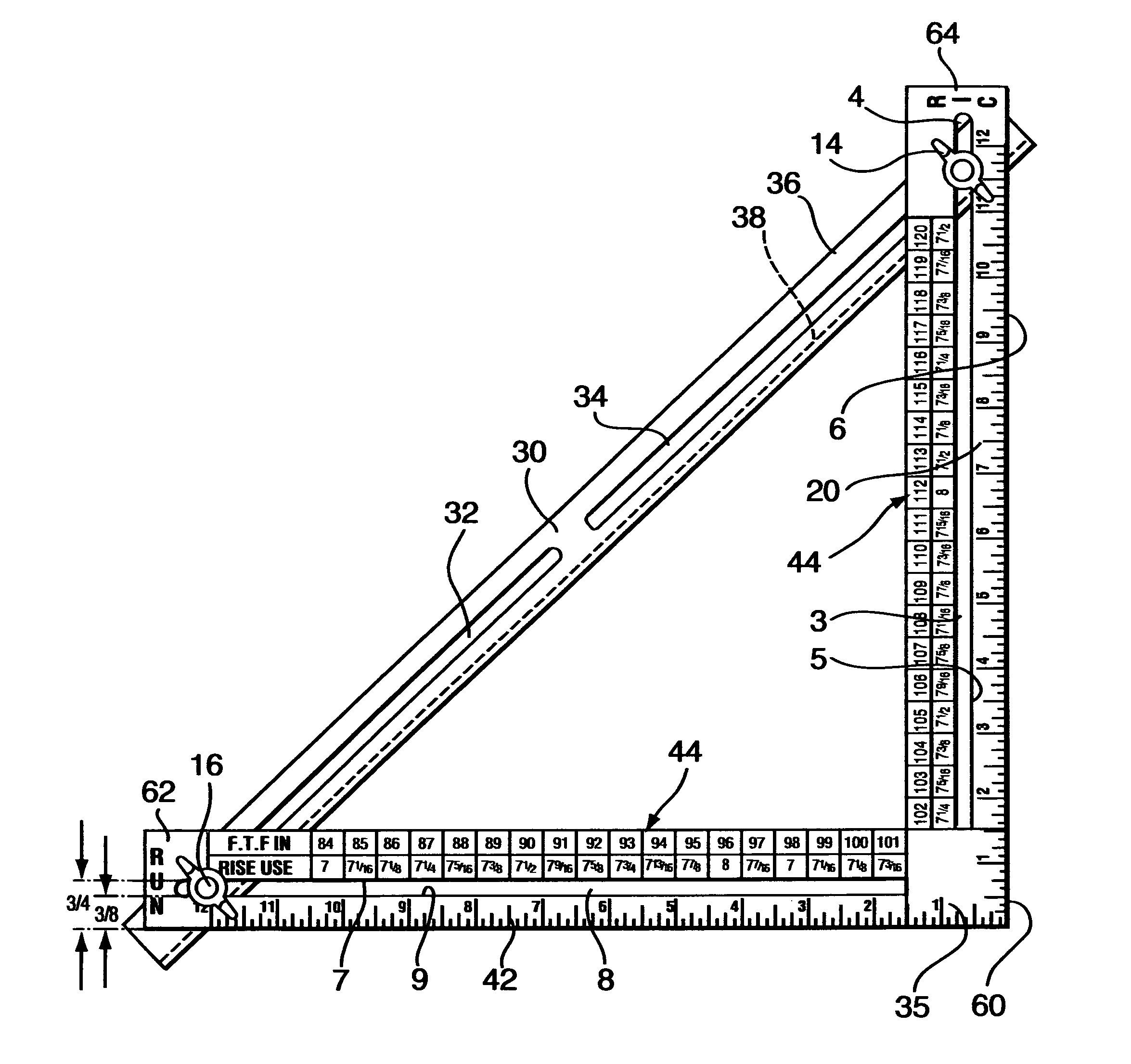
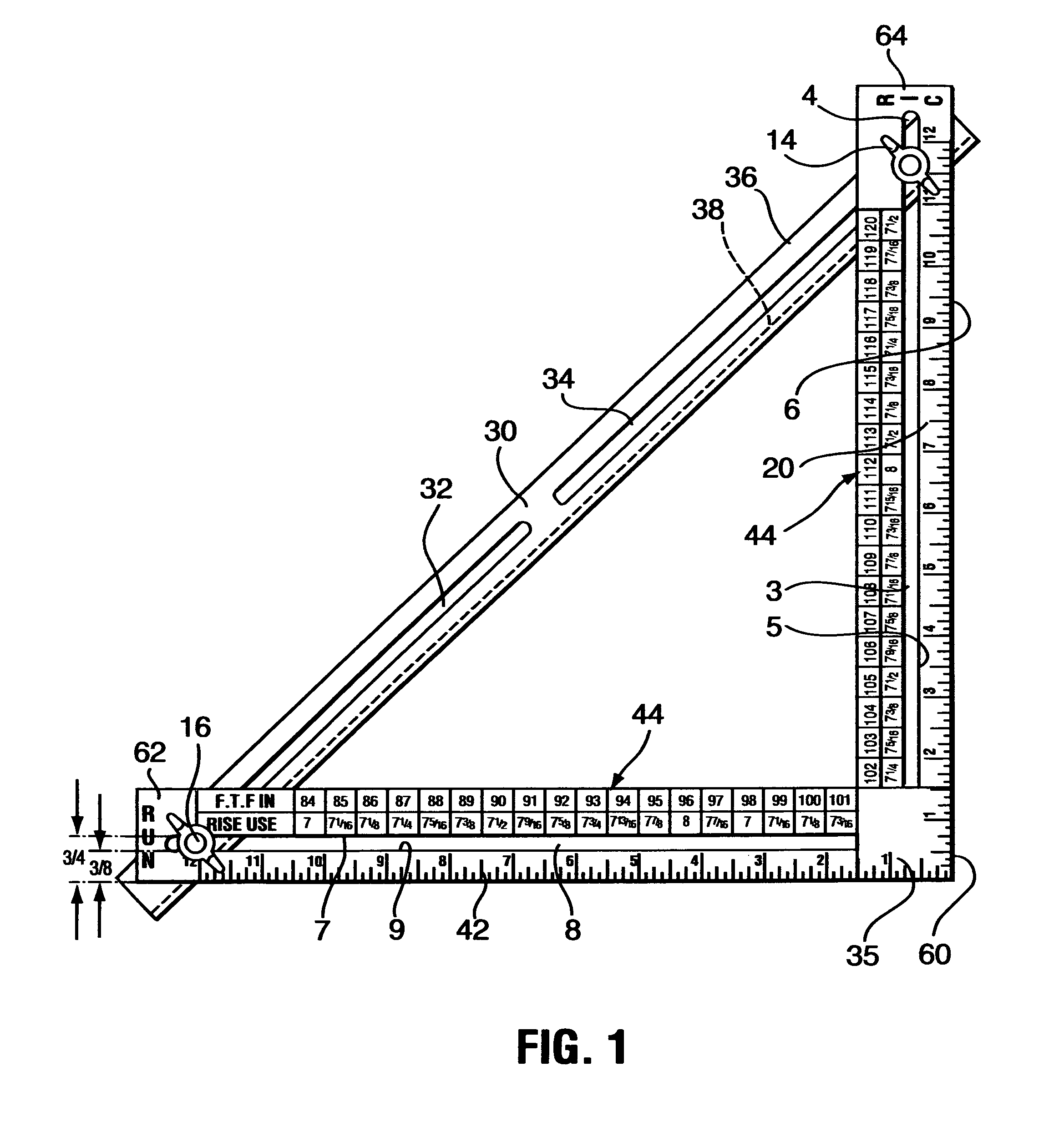
[0028]In accordance with the present invention, there is provided a device step and rafter tool which can be used as a guide to mark cutting lines onto boards intended to be used as stair stringers or as roof rafters.

[0029]When marking a set of stair stringers, the step and rafter tool can be easily adjusted to the correct setting for a particular stair stringer. At that point, the tool can be used to mark all of the step cuts in the stringer without further changes in the setting. The tool ensures that all the steps will be marked the same. The angle bracket maintains the proper angle and the flange extending out from the tool acts as a shoe which is held against and can slide on the narrow side of a board as the user positions the tool to mark the board.

[0030]Likewise, when marking a set of rafters, the tool can be easily adjusted to the correct setting for a particular rafter. At that point, the tool can be used to mark all of the rafters for that part of the roof with that parti...


PUM


Abstract

A tool for use when laying out lines on stair stringers or roof rafters along which cuts are to be made. The step and rafter tool includes a framing square, an angle bracket and two carriage bolts with washers and wingnuts. Each leg of the framing square has a longitudinal slot which is about 90% of the length of the leg. The angle bracket has two central longitudinal slots in the first flange, each of which is about 40% of the length of the angle bracket. The angle bracket is positioned against the framing square so that two carriage bolts are place within holes formed by the overlapping slots of the bracket and square with washers and wingnuts assembled therein. With the wingnuts loose, the angle bracket can be positioned wherever is desired with respect to the framing square and then the wingnuts are tightened. The second flange of the angle bracket now provides a shoe which can slide on the narrow side of a board to be marked and cut for use as a stair stringer or a roof rafter, and thereby stabilize the framing square in place to act as a marking guide. Various indicia, guide marks and data tables are engraved into the legs of the framing square to aid in set up and marking. The edges of the slots in the framing square also provide useful marking guides which are a known distance from other outer or inner edges of the framing square legs.

Description

TECHNICAL FIELD[0001]The present invention relates to framing squares used in marking cut lines for stair stringers, roof rafters and the like.DESCRIPTION OF THE RELATED ART[0002]Framing squares are well known in the art of carpentry. Brackets have been added to framing squares to act as guides or reference edges.[0003]U.S. Pat. No. 327,283 by Levy for “ADJUSTABLE PITCH BOARD FOR SQUARES” which issued on Sep. 29, 1885 teaches tow sliding rulers, one held on each side of a framing square by bolts in slots contained within the scales and the framing square.[0004]U.S. Pat. No. 1,189,983 by McLeod for “FRAMING TOOL” which issued on Jul. 4, 1916 teaches a pair of rulers containing long slots wherein are contained bolt and nut units. The rulers have a framing square captured thereinbetween. The rulers can be positioned on the framing square and tightened. The rulers and framing squares have indicia and marks engraved therein.[0005]U.S. Pat. No. 5,388,340 by Marty for STAIR LAYOUT SQUARE W...

Claims


Application Information

Patent Timeline
Patent Type & Authority Patents(United States)
IPC IPC(8): B43L7/12
CPCB43L7/12B43L7/14E04F21/26E04F21/0076
Inventor FARR, HARVEY H.FARR, WILLIAM H.
Owner FARR HARVEY H
Why Eureka
Try Eureka