Tie rod jam nut

Inactive Publication Date: 2005-03-03
BEATTIE JAMES C
View PDF10 Cites 10 Cited by
  • Summary
  • Abstract
  • Description
  • Claims
  • Application Information

AI Technical Summary

Benefits of technology

[0009] The tie rod jam nut of the present invention allows the quick and easy setting of the toe-in on a vehicle without having to jack up (raise) the vehicle. Since the engagement portio

Problems solved by technology

This is time consuming and preven

Method used


Image

  • Tie rod jam nut
  • Tie rod jam nut
  • Tie rod jam nut

Examples


Example

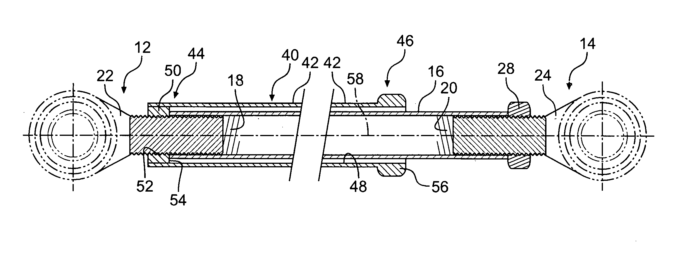
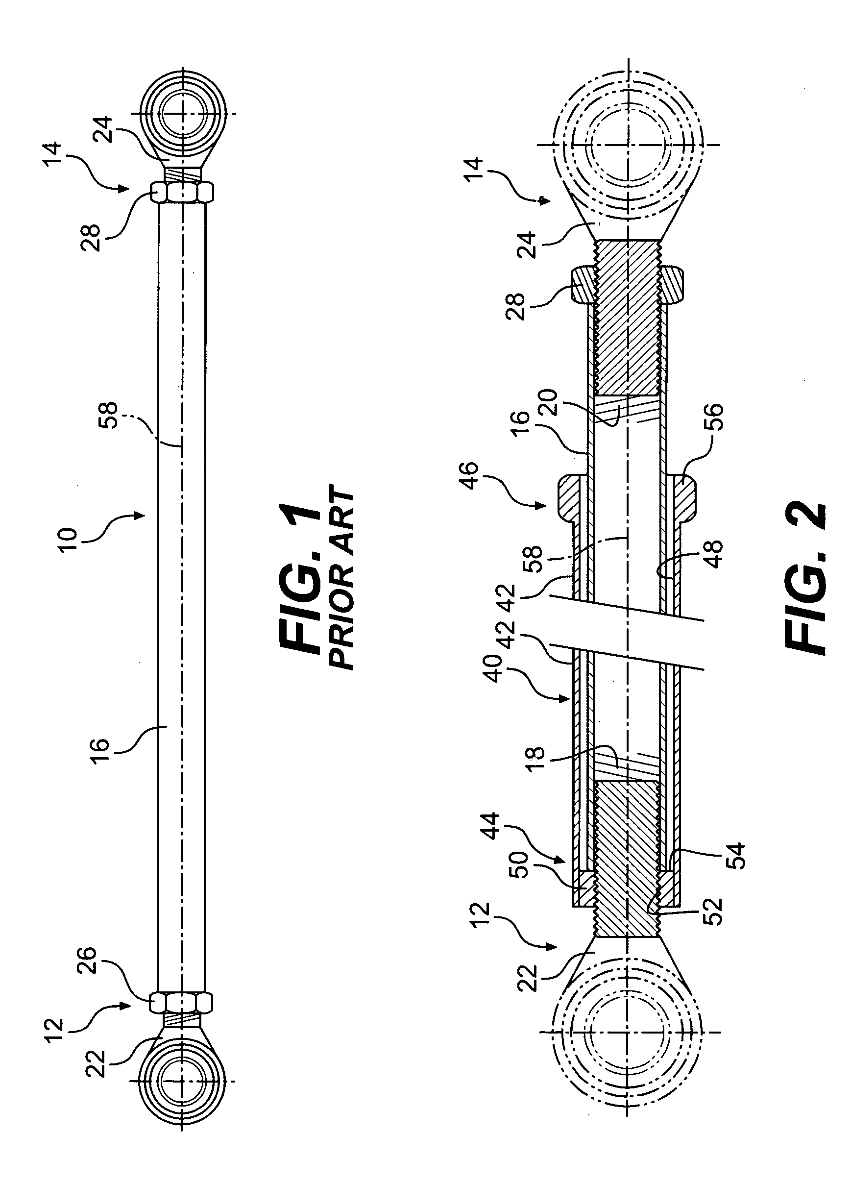
[0015] A tie rod jam nut 40 according to the present invention is shown in partial sectional view in FIG. 2. It replaces the jam nut 26 shown in FIG. 1 and includes an elongated tubular body 42 having a first end 44 and a second end 46. The tubular body has an axially extending internal bore 48 that receives a portion of the tie rod 16. The tie rod jam nut 40 includes a locking portion 50 connected to the first end of the tubular body 42. The locking portion has a threaded bore 52 for engaging the threaded portion of connecting component 22 and a face portion 54 for engaging a portion of the tie rod 16, when the connecting component 22 is screwed into the threaded bore 18 of the tie rod 16. The face portion 54 of the locking portion 50 can thus engage the tie rod 16 so as to lock the connecting component 22 with respect to the tie rod 16 as the locking portion 50 is rotated in a first direction about the threaded portion of the connecting component 22 and disengage the same portion ...


PUM

PropertyMeasurementUnit
Fractionaaaaaaaaaa
Fractionaaaaaaaaaa
Fractionaaaaaaaaaa

Abstract

A tie rod jam nut includes a tubular body having an axial bore for receiving a tie rod. A locking portion at a first end of the body can engage the tie rod and a threaded portion of a connecting component attached to the tie rod to lock the connecting component to the tie rod as the locking portion is rotated in one direction and disengage the tie rod to unlock the connecting component when rotated in an opposite direction. An engagement portion is spaced distally from the locking portion toward a second end of the tubular body. The engagement portion can be rotated to remotely rotate the locking portion between the locked and unlocked positions.

Description

BACKGROUND [0001] In certain machines, tie rods are used to connect two different components together. In an automobile, for instance, a tie rod can be used to connect between a steering box or rack and pinion unit and a wheel steering arm, or between two wheels, among other things. Such tie rods have connectors on one or both ends for connecting to the various components. Such connectors can be in the form of heim joints or tie rod ends that are attached to the tie rod with a threaded connection. In a typical example, the tie rod is tubular and includes an internal threaded bore at one or both ends to receive an externally threaded portion of a connecting component, such as a heim joint or tie rod end. This threaded connection not only connects the connecting component to the tie rod, it also allows the positioning of the connecting component to be adjusted with respect to the tie rod by threading the connecting component in or out of the tie rod, thus altering the effective length...

Claims


Application Information

Patent Timeline
IPC IPC(8): B60G7/00B62D17/00G05G1/00G05G3/00
CPCB60G7/003B62D17/00Y10T74/2142Y10T403/295Y10T29/49927Y10T74/2151Y10T403/24Y10T403/7067Y10T74/18688Y10T403/291
Inventor BEATTIE, JAMES C.
Owner BEATTIE JAMES C
Why Eureka
Try Eureka