
Drop away arrow rest

a drop-away arrow and resting technology, applied in the field of archery, can solve the problems of not offering full containment of arrows and improper seat of arrows in the support, and achieve the effect of simple and efficient, quick and easy setting

Inactive Publication Date: 2015-07-02
GRACE ENG
View PDF6 Cites 12 Cited by
  • Summary
  • Abstract
  • Description
  • Claims
  • Application Information

AI Technical Summary

Benefits of technology

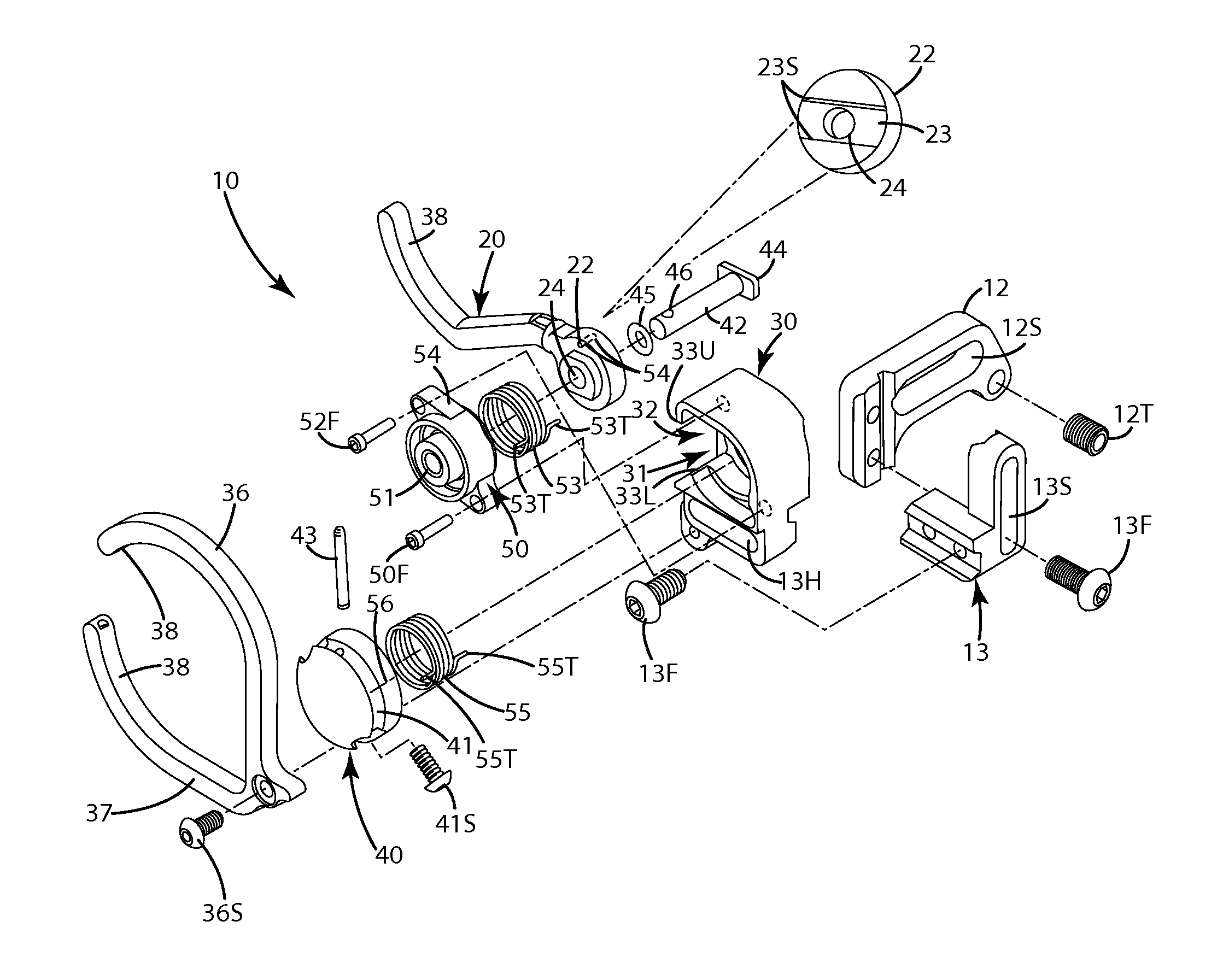
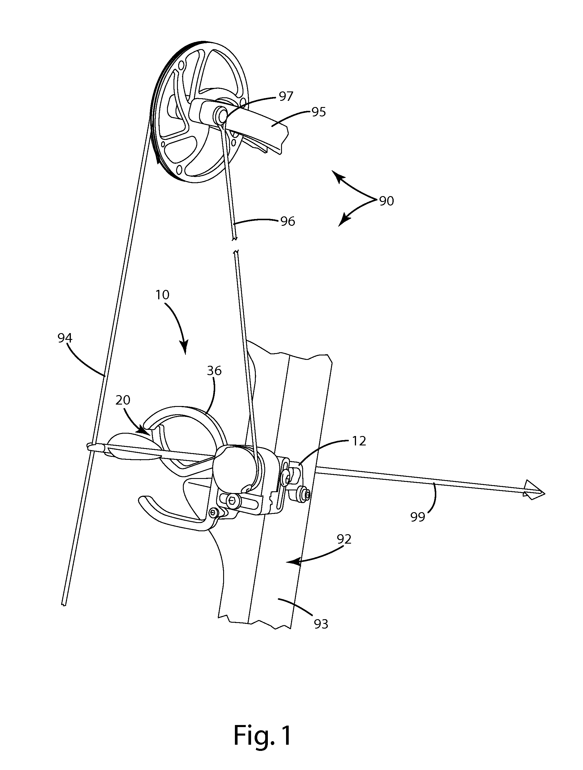
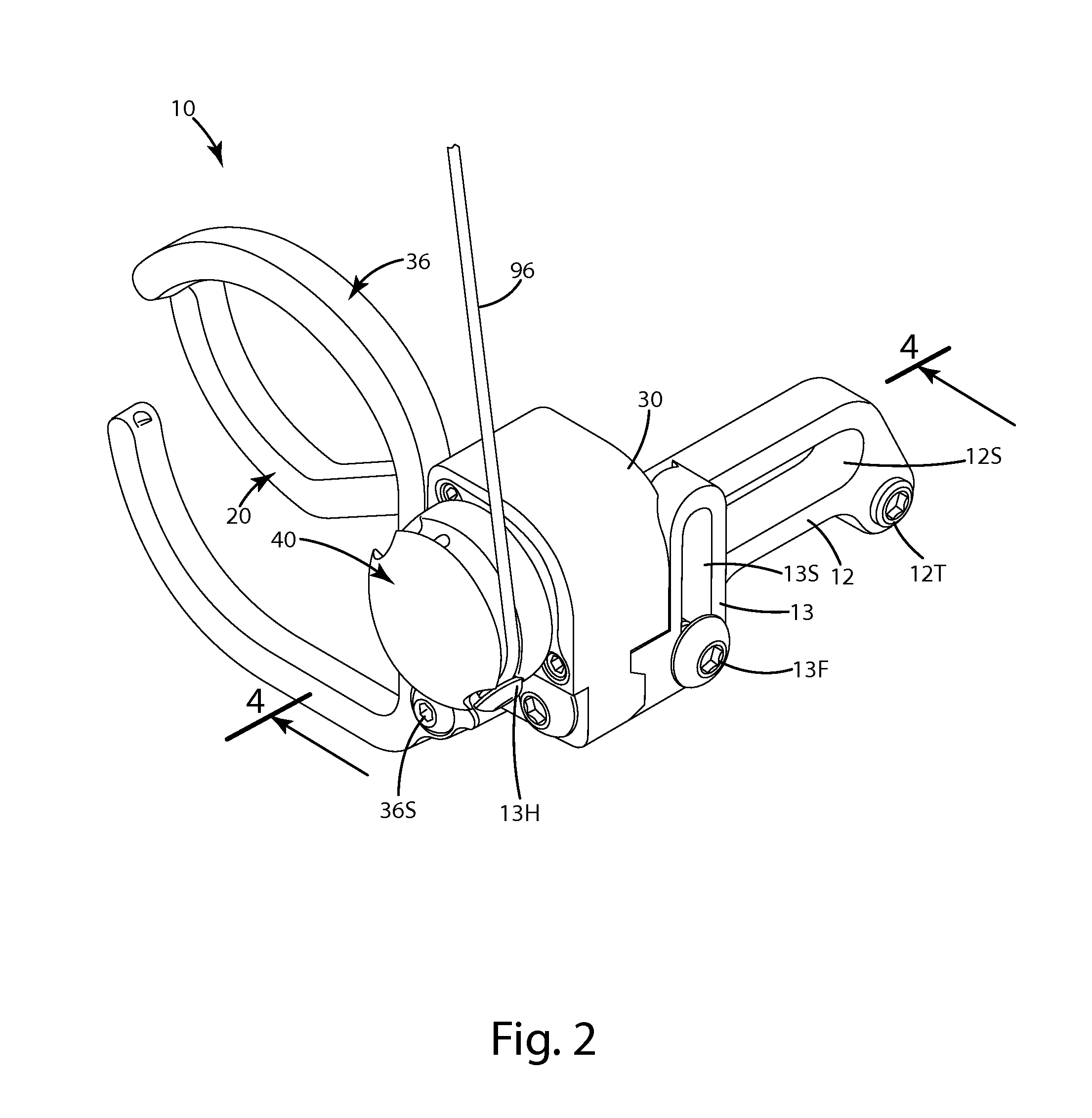
The drop away arrow rest is a simple and efficient mechanism to support a ready to shoot arrow relative to a bow, and rapidly move the support arm of the rest out of the way of the arrow as it is shot. The rest also utilizes movement of other bow components to re-engage internal rest components so that when the bow is shot, the support arm moves efficiently out of the way. The rest includes a support arm that moves about an axis perpendicular to the axis of an arrow, or a vertically moving support arm or bounce back of the support arm and interference with arrow flight, can be eliminated. The rest also includes one or more containment arms, it can impair or prevent the arrow from falling off the rest.

Problems solved by technology

An issue with many drop away rests is that they are configured so that the arrow support normally is positioned in a rest or down position when the bow is undrawn.
Further, sometimes the arrow does not properly seat in the support as it engages the arrow upon drawing.
Another issue with many drop away rests is that they many times do not offer full containment of the arrow.
Yet another issue, particularly with regard to forward falling rests, is that if not properly adjusted, they can bounce back, upward to a support position as the arrow is being shot.

Method used


Image

  • Drop away arrow rest
  • Drop away arrow rest
  • Drop away arrow rest

Examples


first alternative embodiment

III. First Alternative Embodiment

[0078]A first alternative embodiment of the rest is shown in FIG. 11 and generally designated 110. This rest 110 is substantially identical in function and structure to the rest described in the current embodiment above with a few exceptions. For example, the rest 110 includes a mounting bracket 112 and a housing 130. The housing 130 houses and is joined with a reset button 140. The rest button 140 is joined with a rest spring member which is joined with a shaft mount body and a support arm spring within the housing 130. These structures can be identical to those described in connection with the current embodiment of the rest 10 above. The rest 110, however, is set up to include a support arm 120 that includes a forward extending V-portion 120A and a rearward extending V-portion 120B. These portions disengage the arrow 99 upon rotation of the shaft 133 in direction R2. This rest has a rest axis RA-1 that is generally perpendicular to an axis or lengt...

second alternative embodiment

IV Second Alternative Embodiment

[0079]A second alternative embodiment of the arrow rest as shown in FIG. 12 and generally designated 210. This embodiment is similar to that of the current embodiment above in structure and function with a few exceptions. For example, the rest 210 includes a reset button 240, a housing 230 and a shaft 233 extending from the housing 230. The support arm 220 can include a V or U-shaped portion 220A. This embodiment differs from that of the current embodiment of the rest 10 described above in that the rest axis RA-1′ is generally perpendicular to the length or longitudinal axis of the arrow 99, similar to the first alternative embodiment described above. Unlike the first alternative embodiment above, however the support arm 220 includes a U or V-shaped launcher. The launcher moves from the support position to a down or rest position by falling forward in the direction of arrow R3. In turn, this moves the launcher out of the way, and out of contact with t...

third alternative embodiment

V. Third Alternative Embodiment

[0080]A third alternative embodiment of the arrow rest is shown in FIG. 13 and generally designated 310. This arrow rest is similar in structure and function to the current embodiment described above with a few exceptions. For example, this arrow rest 310 is configured so that the support arm 220 drops generally vertically in the direction of the arrow under the arm from the support position to a rest position where the arm 220 is substantially lowered as shown in broken lines in FIG. 14. The rest 310 can include a housing 330 and a reset button 340. The reset button and internal components of the rest are arranged to rotate about and / or move relative to the rest axis RA2. The housing 330 also can include a redirector 333 so that a cord 96 extending upwardly to a movable bow component can translate movement of that component to rotation of the reset button 340. This rest also includes a support arm 220. The support arm is different from those of the em...


PUM


Abstract

A drop away arrow rest including an arrow support arm and a reset button operable to convert the rest from a first mode, in which a shaft is rotationally fixed relative to the support arm, to a second mode, in which the shaft is rotationally decoupled relative to the support arm. The reset button can be manually moveable to convert the rest from the first mode in which the support arm can be in a rest position, to the second mode in which the support arm can be in the support position. The rest can include a reset bias member that selectively moves the shaft, and a support arm bias member that selectively moves the support arm to the support position and / or the rest position. The rest can include containment arms to offer full, surrounding arrow containment. A readily replaceable bumper can join with the support arm and / or containment arms.

Description

BACKGROUND OF THE INVENTION[0001]The present invention relates to an archery drop away arrow rest and a related method of operation.[0002]Most archery bows are equipped with an arrow rest that holds an arrow before it is shot from the bow. One common arrow rest is referred to as a “drop away” arrow rest. This rest precisely and accurately positions the arrow when the bow (and thus, the bowstring) is at full draw, but drops rapidly away from the arrow upon release of the bowstring. Accordingly, the rest does not contact the arrow for its full length or the arrow's fletching and divert the arrow from its intended trajectory as the arrow is shot from the bow.[0003]A variety of drop away arrow rests exist. One type of rest is a forward falling rest. A forward falling rest typically includes (a) an arrow support that holds the arrow shaft in a loaded position at full draw and subsequently drops forward or falls away forward (away from the archer / bowstring) to a relaxed position upon rele...

Claims


Application Information

Patent Timeline
Patent Type & Authority Applications(United States)
IPC IPC(8): F41B5/14
CPCF41B5/143
Inventor GRACE, NATHANIEL E.ROELENS, II, TIMOTHY J.
Owner GRACE ENG
Learn More