Device for sensing cardiac activity in an implantable medical device in the presence of magnetic resonance imaging interference

a magnetic resonance imaging and cardiac activity technology, applied in the field of implantable medical devices, can solve the problems of increasing the complexity and functional sophistication the vulnerability of conventional implantable medical device systems to more sophisticated and complex sources of interference, and the increase of implantable medical device systems

Inactive Publication Date: 2006-07-11
MEDTRONIC INC
View PDF29 Cites 187 Cited by
  • Summary
  • Abstract
  • Description
  • Claims
  • Application Information

AI Technical Summary

Problems solved by technology

Today's state-of-the-art implantable medical devices are vastly more sophisticated and complex than earlier ones.
As the functional sophistication and complexity of implantable medical device systems have increased over the years, however, the conventional implantable medical device systems have also been found to be vulnerable to more sophisticated and complex sources of interference.
In particular, the conventional implantable medical device systems have been found to be vulnerable to electromagnetic interference signals produced by magnetic resonance imaging (MRI) devices during a magnetic resonance imaging (MRI) scanning session.
For example, when a patient having an implantable medical device is subjected to a magnetic resonance imaging (MRI) scanning session, the implantable medical device's sensed voltage signal may be distorted and / or corrupted so that an accurate assessment of the cardiac rhythm and / or function becomes more difficult.
During a magnetic resonance imaging (MRI) scanning session, the implantable medical device's sensed atrial / ventricular (A / V) electrograms (voltage measurements) may be distorted and / or corrupted so that an accurate assessment of the cardiac rhythm and / or function becomes more difficult.
However, disabling the sensing circuit necessarily prevents an accurate assessment of the cardiac rhythm and / or function using the sensing circuit.
As a result, more sophisticated therapies that may rely on the detection of cardiac activity may not function properly when the sensing circuit has been disabled.

Method used


Image

  • Device for sensing cardiac activity in an implantable medical device in the presence of magnetic resonance imaging interference
  • Device for sensing cardiac activity in an implantable medical device in the presence of magnetic resonance imaging interference
  • Device for sensing cardiac activity in an implantable medical device in the presence of magnetic resonance imaging interference

Examples


Embodiment Construction

[0031]Illustrative embodiments of the invention are described below. In the interest of clarity, not all features of an actual implementation are described in this specification. It will of course be appreciated that in the development of any such actual embodiment, numerous implementation-specific decisions must be made to achieve the developers' specific goals, such as compliance with system-related and business-related constraints, which will vary from one implementation to another. Moreover, it will be appreciated that such a development effort might be complex and time-consuming, but would nevertheless be a routine undertaking for those of ordinary skill in the art having the benefit of this disclosure.

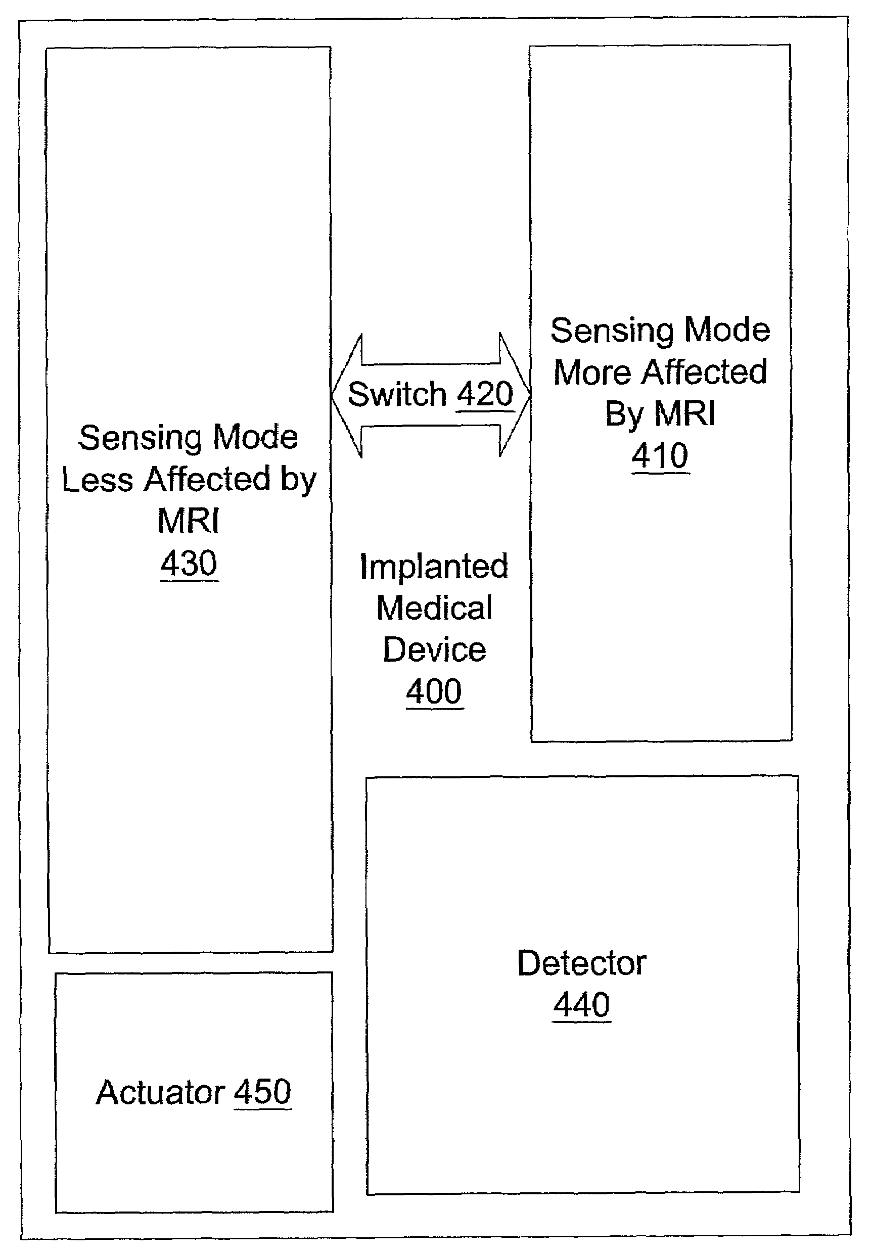
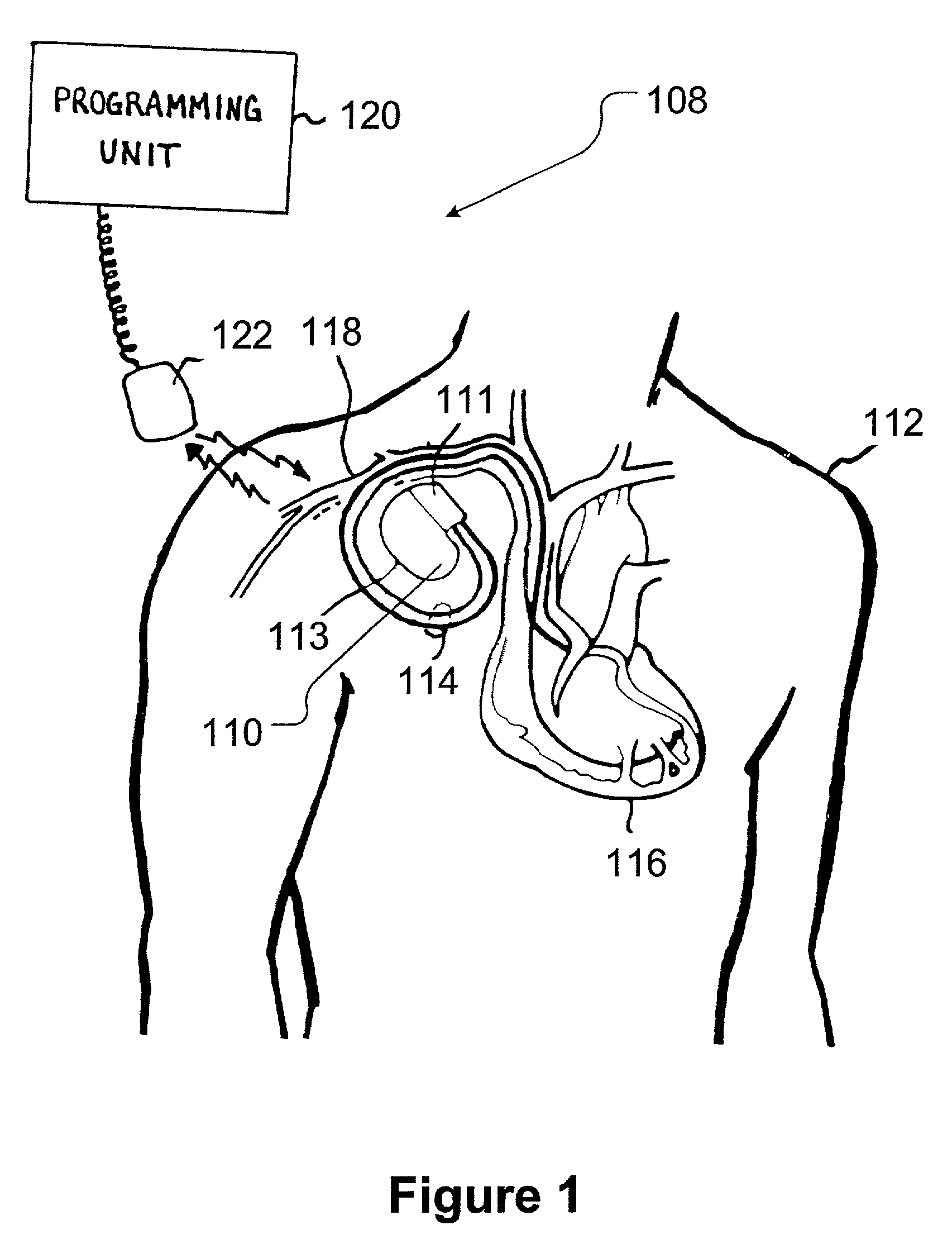
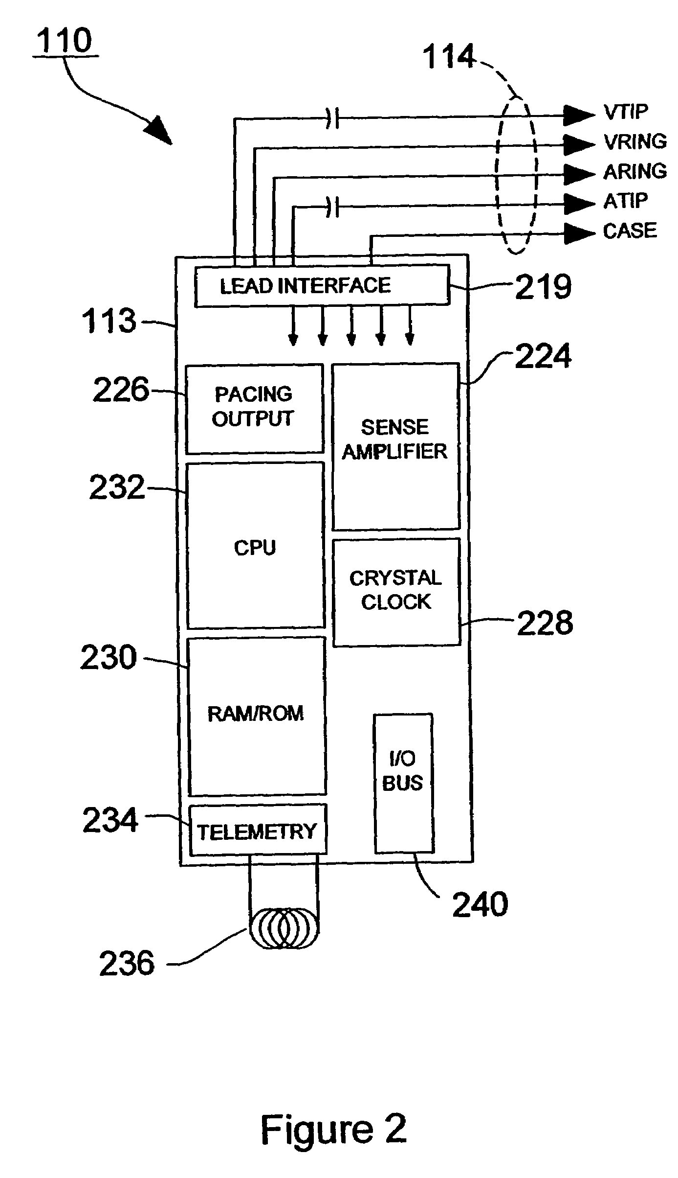
[0032]Illustrative embodiments of an apparatus and a method for operation of the apparatus according to the present invention are shown in FIGS. 1–19. FIG. 1 illustrates an implantable medical device (IMD) system 108, which includes, for example, an implantable pacemaker 110 that...


PUM


Abstract

A method is provided, the method comprising detecting a magnetic resonance imaging (MRI) interference signal and enabling at least one preventive measure to protect an implantable medical device from interference by the magnetic resonance imaging (MRI) interference signal. The method also comprises switching from a first sensing mode more affected by the magnetic resonance imaging (MRI) interference signal to a second sensing mode less affected by the magnetic resonance imaging (MRI) interference signal.

Description

FIELD OF THE INVENTION[0001]This invention relates generally to implantable medical devices and, more particularly, to protecting implantable medical devices from interference by magnetic resonance imaging (MRI) interference signals.DESCRIPTION OF THE RELATED ART[0002]Since the introduction of the first implantable pacemakers in the 1960s, there have been considerable advances in both the fields of electronics and medicine, such that there is presently a wide assortment of commercially available body-implantable electronic medical devices. The class of implantable medical devices now includes pacemakers, implantable cardioverters, defibrillators, neural stimulators, and drug administering devices, among others. Today's state-of-the-art implantable medical devices are vastly more sophisticated and complex than earlier ones. Today's state-of-the-art implantable medical devices are capable of performing significantly more complex tasks. The therapeutic benefits of such devices have bee...

Claims


Application Information

Patent Timeline
Patent Type & Authority Patents(United States)
IPC IPC(8): A61B5/05A61N1/365A61N1/37
CPCA61N1/3702A61N1/36514Y10S128/901A61N1/3718
Inventor CHO, YONG KYUNKALIN, RONREINKE, JAMES D.
Owner MEDTRONIC INC
Why Eureka
Try Eureka