Cover for terminal screws of a receptacle

Inactive Publication Date: 2006-07-18
SUN LITE SOCKETAB IND
View PDF6 Cites 17 Cited by
  • Summary
  • Abstract
  • Description
  • Claims
  • Application Information

AI Technical Summary

Benefits of technology

[0005]The prime object of this invention is to offer a cover to cover on terminal screws of a receptacle

Problems solved by technology

Because the terminal screws 12 are always exposed without any protection, they are very apt to contact with the fixing box or other exterior objects when the receptacle 10 is put

Method used


Image

  • Cover for terminal screws of a receptacle
  • Cover for terminal screws of a receptacle
  • Cover for terminal screws of a receptacle

Examples


Embodiment Construction

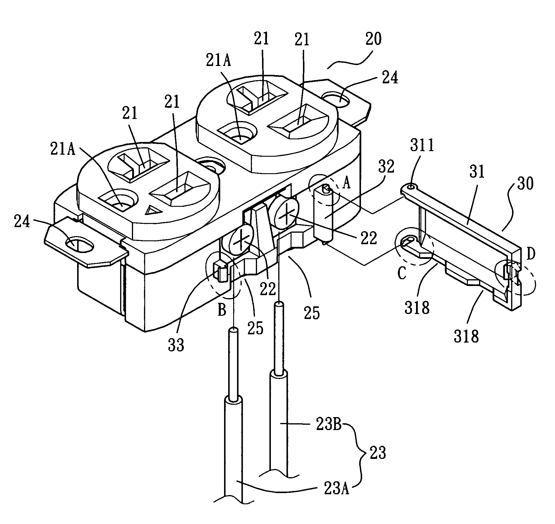
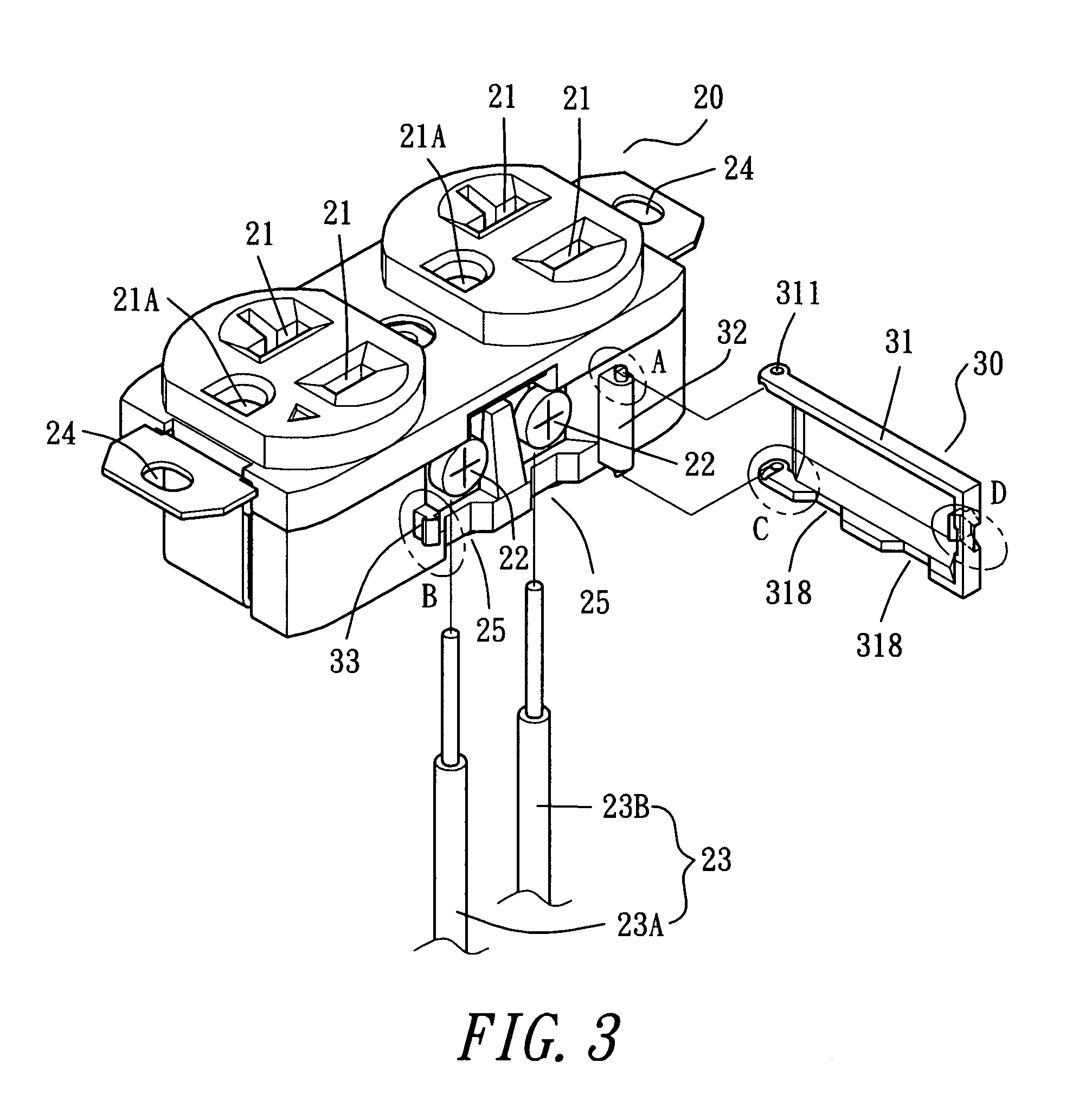
[0022]FIG. 3 shows a preferred embodiment of a cover 30 for terminal screws of a receptacle in the present invention, and the receptacle includes a receptacle 20 and the cover 30.

[0023]The receptacle 20 is provided with plural sets of plughole 21 in an upper surface to be inserted by the feet of a plug. A third plughole 21A is to be inserted by the third foot of a plug, if the plug has it, for grounding. Each hole of the plughole 21 is respectively fixed with a positive pole or a negative pole extending to holes in a sidewall of the receptacle 20, connected with terminal screws 22 with power lines 23. A power line 23A for an input and the other power line 23B is for an output to be connected to another utility, if necessary. In other words, the power line 23 can be one or two with the one 23A being necessary and the other 23B being optional. At the bottom edge of the receptacle 20 where the power lines 23 passes is formed with a recessed groove 25 to let the power lines 23 pass thro...


PUM


Abstract

A cover for terminal screws of a receptacle, which has plug holes with a positive and a negative pole connected with terminal screws with a power line, is composed of a pivotal column, a locking hook and a cover case. The pivotal column is fixed on a sidewall of the receptacle, having a pivotal pin on its top and its bottom. The locking hook is fixed on the other side of the pivotal column on the sidewall. The cover case has a flat projection on the top and the bottom of its inner side, with each flat projection bored with a locking hole, and a locking bar with a rear opening provided at its other side. Then the pivotal pins may insert in the pivotal holes of the flat projections, and the locking bar is to lock with the locking hook, which is then to be confined in the opening, enabling the cover case to close stably on the terminal screws.

Description

BACKGROUND OF THE INVENTION[0001]1. Field of the Invention[0002]This invention relates to a cover for terminal screws of a receptacle, particularly to one combined on a sidewall of a receptacle where terminal screws to be connected with a power line is located, and able to cover on the terminal screws to keep them from being contacted with other objects for preventing any accident like short-circuits or sparking.[0003]2. Description of the Prior Art[0004]A common conventional receptacle 10, as shown in FIGS. 1 and 2, is provided with plug holes 11 set on its front surface. Each of the plugholes 11 is connected through each other by a positive line and a negative line respectively inside the receptacle 10. Then, the positive line and the negative line are pulled out from one sidewall of the receptacle 10 and connected by terminal screws 12 with input and output currents of the power line 13. In installation, the power line 13 is first connected with the receptacle 10 with the termina...

Claims


Application Information

Patent Timeline
IPC IPC(8): H01R31/00
CPCH01R4/34H01R13/447H01R25/006H01R24/76H01R2103/00
Inventor YANG, WEN HO
Owner SUN LITE SOCKETAB IND
Why Eureka
Try Eureka