Image forming apparatus

Active Publication Date: 2006-07-18
HEWLETT PACKARD DEV CO LP
View PDF8 Cites 27 Cited by
  • Summary
  • Abstract
  • Description
  • Claims
  • Application Information

AI Technical Summary

Benefits of technology

[0010]Accordingly, it is an aspect of the present invention to provide an improved image forming

Problems solved by technology

Furthermore, there may be difficulty i

Method used


Image

  • Image forming apparatus
  • Image forming apparatus
  • Image forming apparatus

Examples


Embodiment Construction

[0026]Reference will now be made in detail to the present preferred embodiments of the present invention, examples of which are illustrated in the accompanying drawings, wherein like reference numerals refer to like elements throughout.

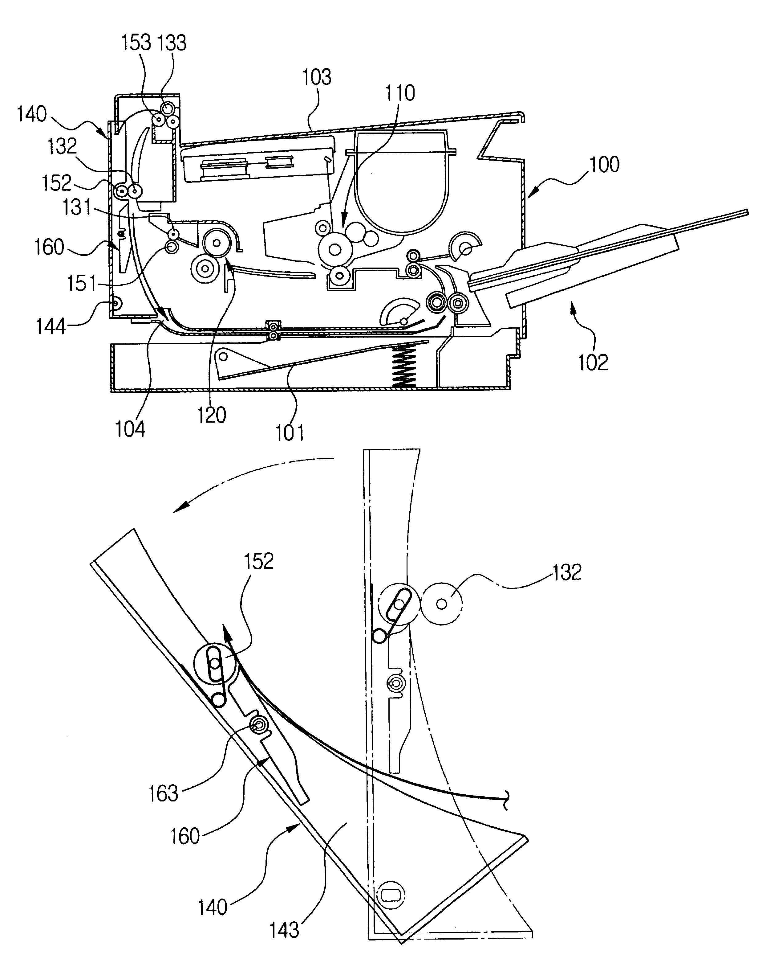
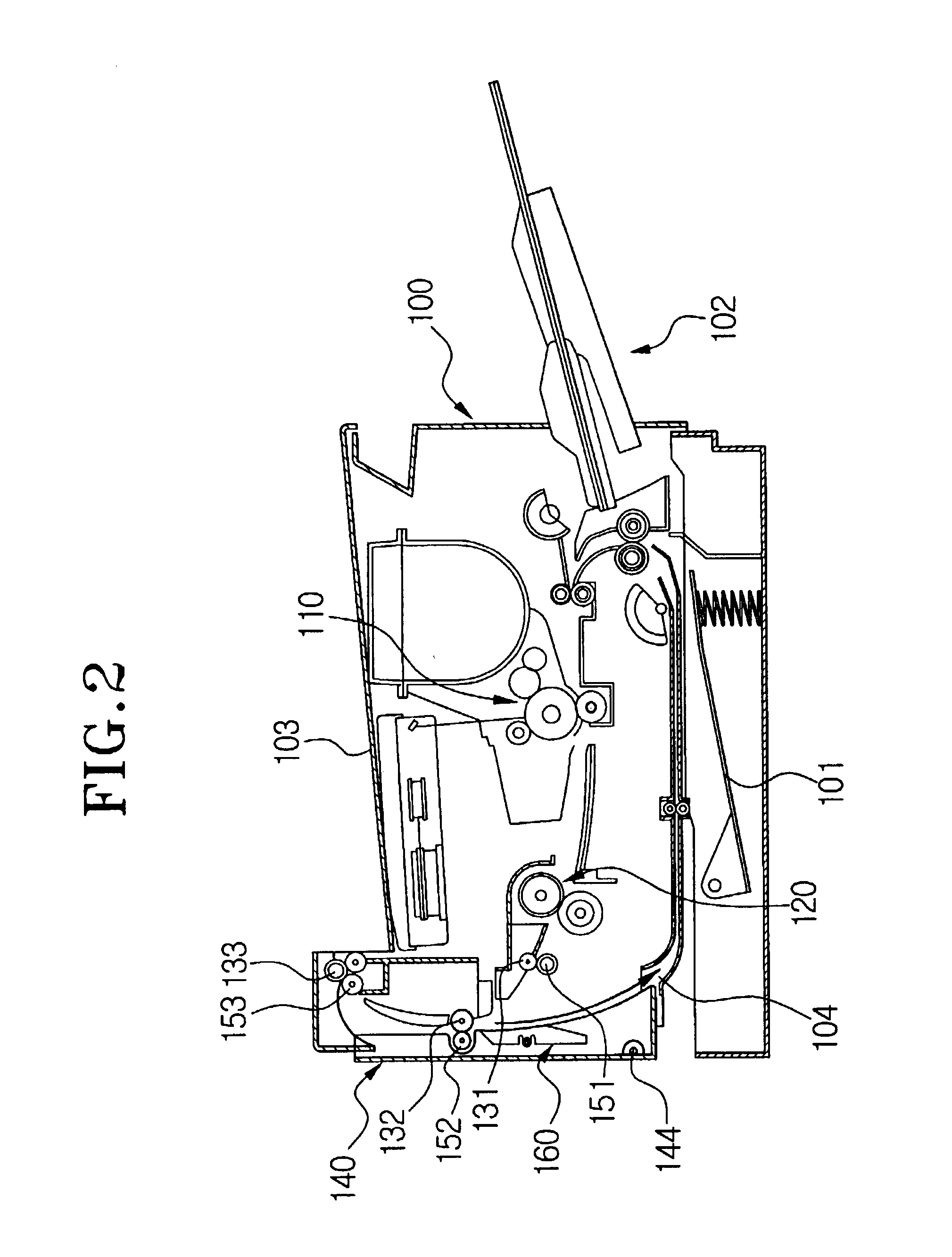
[0027]Referring to FIG. 2, an image forming apparatus, according to an embodiment of the present invention includes a printer body 100 provided with a developing portion 110 and a fixing portion 120 disposed therein, a plurality of sheet feeding rollers 131, 132 and 133, a rear cover 140 disposed at a rear side of the printer body 100 to open and close, an idle roller 152 rotatably disposed at the rear cover 140, and a supplementary guide member 160 rotatably disposed at the rear cover 140.

[0028]The printer body 100 is provided with a sheet supply cassette 101 disposed at a lower part thereof, and a manual sheet supply portion 102 disposed at a front side thereof. Since the constitutions of the developing portion 110 and the fixing portion 120 are ide...


PUM


Abstract

An image forming apparatus includes a printer body having a developing portion and a fixing portion therein, a plurality of sheet feeding rollers provided along a sheet discharge path successively and driven to discharge a sheet passing through the fixing portion to an upper portion of the printer body, and a rear cover provided on a side of the printer body to open and close, and having guide ribs to guide the sheet passed through the fixing portion. The image forming apparatus also includes an idle roller provided movably on the rear cover, to contact and rotate with one of the sheet feeding rollers to feed the sheet, and a supplementary guide member provided rotatably on the rear cover and positioned below the idle roller. The supplementary guide member changes a position thereof when the rear cover is open so that the sheet being discharged directly to the guide ribs is prevented from running into the idle roller.

Description

CROSS REFERENCE TO RELATED APPLICATION[0001]This application claims the benefit of Korean Application No. 2002-44252, filed Jul. 26, 2002, in the Korean Intellectual Property Office, the disclosure of which is incorporated herein by reference.BACKGROUND OF THE INVENTION[0002]1. Field of the Invention[0003]The present invention relates to an image forming apparatus and, more particularly, to an image forming apparatus to prevent sheets from running into an idle roller during a discharge of special sheets.[0004]2. Description of the Related Art[0005]Referring to FIG. 1, a conventional image forming apparatus is provided with a sheet supply cassette 11 in which sheets are stacked on a lower end of a body 10. The sheets in the sheet supply cassette 11 are picked up one after another by a pickup roller 12. The picked up sheets are sent to a developing portion 13. The developing portion 13 includes a photosensitive drum 14, a developing roller 15 and a transfer roller 16. The photosensiti...

Claims


Application Information

Patent Timeline
IPC IPC(8): G03G15/00B65H5/36
CPCG03G15/6573G03G15/00
Inventor BAEK, JUNG-GEEKIM, DONG-WOO
Owner HEWLETT PACKARD DEV CO LP
Why Eureka
Try Eureka